TM3SAK6R / TM3SAK6RG Characteristics
This section provides a description of the characteristics of TM3SAK6R / TM3SAK6RG safety modules.
See also Environmental Characteristics.
|
|
|
UNINTENDED EQUIPMENT OPERATION |
|
Do not exceed any of the rated values specified in the environmental and electrical characteristics tables. |
|
Failure to follow these instructions can result in death, serious injury, or equipment damage. |
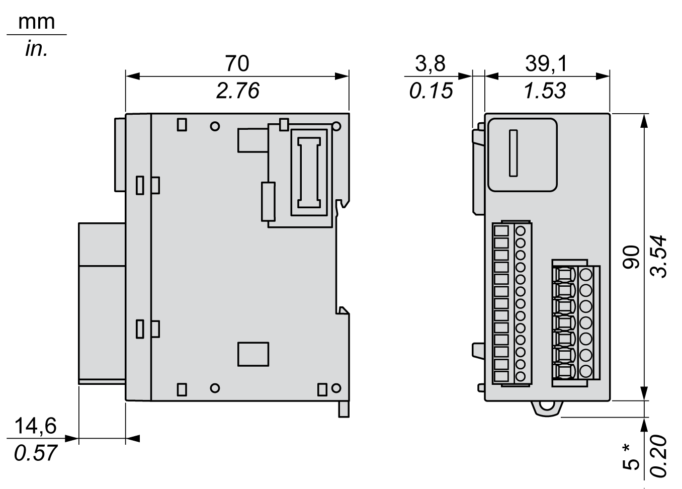
This diagram shows the external dimensions of the TM3SAK6R / TM3SAK6RG safety modules:

* 8.5 mm (0.33 in.) when the clamp is pulled out.
The TM3SAK6R• module is a safety module for monitoring emergency stop and limit switches on protective guards, safety light curtains, and safety-mats according to ISO/EN 13849, IEC/EN 62061, IEC/EN 61058. The module has these safety-related characteristics:
|
Characteristic |
Value |
Designed to specification |
|---|---|---|
|
Safety integrity level (SIL) |
3 |
IEC/EN 61508-1:2010 |
|
Safety integrity level claim limit (SILCL) |
3 |
IEC/EN 62061:2005 |
|
Safe failure fraction (SFF) |
95 % |
IEC/EN 61508-1:2010 |
|
Hardware fault tolerance (HFT) |
1 |
IEC/EN 61508-1:2010 |
|
Type |
A |
IEC/EN 61508-1:2010 |
|
Mode of operation |
High demand mode |
IEC/EN 61508-1:2010 |
|
Probability of dangerous failures per hour (PFHd) |
30 * 10-9 / h (1) |
IEC/EN 61508-1:2010 |
|
5 * 10-9 / h (2) |
||
|
Mean time to dangerous failure (MTTFd) |
85 years (1) |
ISO/EN 13849-1:2008 |
|
500 years (2) |
||
|
Performance level (PL) category (cat.) |
PL e. cat. 4 |
ISO/EN 13849-1:2008 |
|
Diagnostic coverage (DC) |
95 % |
ISO/EN 13849-1:2008 |
|
Lifetime |
20 years |
– |
|
Response time |
20 ms |
– |
|
Proof test interval (PTI) |
None |
– |
|
Stop category |
0 |
IEC/EN 60204-1 |
|
Start |
Manual or automatic |
– |
|
Paths |
• 3 enabling paths • 1 signaling path |
– |
|
Feedback |
Feedback loop to monitor external contactors. |
– |
|
Defined safe state |
The TM3 safety modules are in the defined safe state when their outputs are off (internal relays are not energized; output path is open). |
– |
|
NOTE: These modules contain electromechanical relays, so actual MTTFd and PFHd values vary depending on the application load and duty cycle. (1) 60 operation cycles per hour at DC-13 24 Vdc 1 A (2) 1 operation cycle per hour at DC-13 24 Vdc 4 A |
||
This table describes the power supply characteristics of the TM3 safety module:
|
Characteristic |
Value |
|
|---|---|---|
|
Supply voltage |
IEC 60038 |
24 Vdc -15...+20 % |
|
External fuse protection (maximum) |
4 A slow blow (class gG) |
|
|
Power consumption |
24 Vdc supply voltage |
3.6 W |
|
TM3 Bus (5 Vdc) |
0.2 W |
|
This table describes the control circuit characteristics of the TM3 safety module:
|
Characteristic |
Value |
|
|---|---|---|
|
Input voltage (high) (1) |
Minimum |
19.6 Vdc |
|
Nominal |
24 Vdc |
|
|
Maximum |
28.8 Vdc |
|
|
Input voltage (low) (1) |
Minimum |
0 Vdc |
|
Nominal |
0 Vdc |
|
|
Maximum |
2 Vdc |
|
|
Input current (high) (1) |
Nominal |
35 mA |
|
Maximum |
80 mA |
|
|
Input current (low) (1) |
Nominal |
0 mA |
|
Maximum output current from control circuit terminals: S11, S31, S22 |
100 mA |
|
|
Nominal voltage at the pins |
24 Vdc |
|
|
Response time |
≤ 20 ms |
|
|
Delay |
On |
≤ 100 ms |
|
Restart |
≤ 300 ms |
|
|
(1) At terminal S12, S32 when externally supplied |
||
This table describes the output circuit characteristics of the TM3 safety module:
|
Characteristic |
Value |
|
|---|---|---|
|
Maximum switching current of each output |
AC-15: 230 Vac |
5 A |
|
DC-13: 24 Vdc |
4 A |
|
|
Minimum switching voltage and current (new contact never used with higher loads) |
17 V, 10 mA |
|
|
Maximum current |
Per output path |
6 A |
|
Sum of current in all output paths |
≤ 18 A |
|
|
External fuse protection (maximum) |
Slow blow (class gG) fuse |
4 A |
|
Fast blow fuse |
6 A |
|
|
Maximum switching operations |
107 |
|