SF_EmergencyStop
The following description is valid for the function block SF_EmergencyStop_V1_0z, Version 1.0z (where z = 0 to 9).
Short description
|
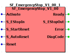
The safety-related SF_EmergencyStop function block monitors the switching states of an emergency-stop control device. When the connected emergency-stop device is activated, the enable signal at output S_EStopOut becomes SAFEFALSE. S_StartReset can be used to specify a start-up inhibit and S_AutoReset can be used to specify a restart inhibit. |
|
Function block inputs
Click the corresponding hyperlinks to obtain detailed information on the items below.
|
Name |
Short description |
Value |
|---|---|---|
|
State-controlled input for activating the function block. Data type: BOOL Initial value: FALSE |
|
|
|
State-controlled input for the status of the emergency-stop control device. Data type: SAFEBOOL Initial value: SAFEFALSE |
|
|
|
State-controlled input for specifying the start-up inhibit after the Safety Logic Controller has been started up or the function block has been activated. An active start-up inhibit must be removed manually by means of a positive signal edge at the Reset input. A deactivated start-up inhibit causes the S_EStopOut output to switch to SAFETRUE automatically when the function block is activated and the safety-related function is not requested. Data type: SAFEBOOL Initial value: SAFEFALSE Refer to the first hazard message below this table. |
|
|
|
State-controlled input for specifying the restart inhibit after the SAFETRUE signal has returned at the S_EStopIn input, i.e., after the previously activated emergency-stop control device has been deactivated again. An active restart inhibit must be removed manually by means of a positive signal edge at the Reset input. A deactivated restart inhibit causes the S_EStopOut output to switch to SAFETRUE automatically when the function block is activated and the safety-related function is no longer requested. Data type: SAFEBOOL Initial value: SAFEFALSE Refer to the first hazard message below this table. |
|
|
|
Edge-triggered input for the reset signal:
Refer to the second hazard message below this table. Data type: BOOL Initial value: FALSE
NOTE:
Resetting does not occur with a negative (falling) edge, as specified by standard EN ISO 13849-1, but with a positive (rising) edge. |
|
| WARNING | |
|---|---|
Resetting the function block by means of a positive signal edge at the Reset input can cause the S_EStopOut output to switch to SAFETRUE immediately (depending on the status of the other inputs).
| WARNING | |
|---|---|
Function block outputs
Click the corresponding hyperlinks to obtain detailed information on the items below.
|
Name |
Short description |
Value |
|---|---|---|
|
Output for signaling "Function block activated/not activated". Data type: BOOL |
|
|
|
Output for enable signal of the function block. Data type: SAFEBOOL |
|
|
|
Output for error message. Data type: BOOL |
|
|
|
Output for diagnostic message. Data type: WORD |
Diagnostic message of the function block. The possible values are listed and described in the topic "Diagnostic codes". |
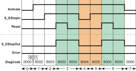
Signal sequence diagram
This diagram relates to a typical emergency-stop function with an active start-up inhibit and an active restart inhibit:
-
S_StartReset = SAFEFALSE: Start-up inhibit after the function block has been activated and the Safety Logic Controller has started up
-
S_AutoReset = SAFEFALSE: Restart inhibit after the connected emergency-stop control device has been deactivated (SAFETRUE signal returns at the S_EStopIn input)
The other signal sequence diagram can be taken into account.
The signal sequence diagrams in this documentation possibly omit particular diagnostic codes. For example, a diagnostic code is possibly not shown if the related function block state is a temporary transition state and only active for one cycle of the Safety Logic Controller.
Only typical input signal combinations are illustrated. Other signal combinations are possible.
|
0 |
The function block is not yet activated (Activate = FALSE). As a result, all outputs are FALSE or SAFEFALSE. |
|
1 |
After the function block has been activated by Activate = TRUE, the start-up inhibit is active at first. |
|
2 |
The previously activated emergency-stop control device is deactivated (N/C contacts closed). The S_EStopOut output remains SAFEFALSE at first, as S_StartReset = SAFEFALSE prevents automatic start-up. |
|
3 |
Positive signal edge at the Reset input removes the start-up inhibit, followed by normal operation. The S_EStopOut output becomes SAFETRUE. |
|
4 |
Emergency-stop request. The control device is activated. The S_EStopOut output becomes SAFEFALSE. |
|
5 |
The emergency-stop control device is deactivated again and the S_EStopOut output remains SAFEFALSE at first, as the restart inhibit has been specified by S_AutoReset = SAFEFALSE. |
|
6 |
Positive signal edge at the Reset input removes the start-up inhibit, followed by normal operation. The S_EStopOut output becomes SAFETRUE. |
|
7 |
The function block activation is reset (Activate = FALSE), S_EStopOut output = SAFEFALSE. |
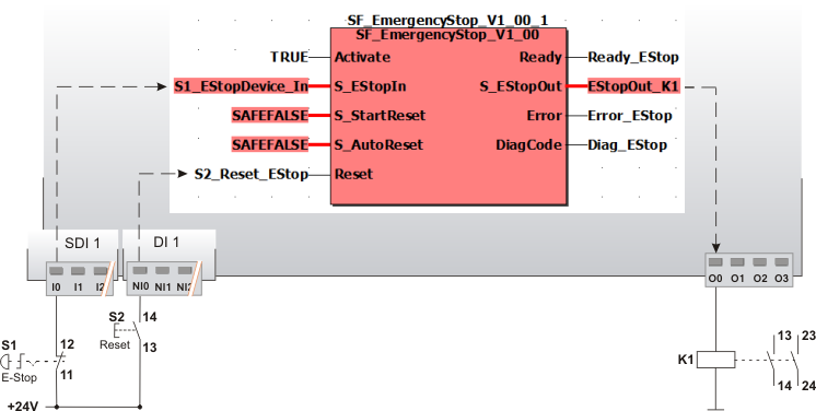
Application example
This example illustrates a single-channel connection of the N/C contact of an emergency-stop control device S1 with the safety-related SF_EmergencyStop function block. The emergency-stop control device is connected to input terminal I0 of the safety-related input device SDI with an ID of 1.
In this example the following applies:
-
The signal of the input terminal I0 of the safety-related input device SDI 1 is assigned to the global I/O variable S1_EStopDevice_In. This global I/O variable is connected to the S_EStopIn input of the function block for evaluation.
-
The global I/O variable EStopOut_K1 is connected to output S_EStopOut of the function block. This global I/O variable has the O0 output terminal of the Safety Logic Controller as address.
The function block is perpetually activated by the TRUE constant at the Activate input.
S_StartReset = SAFEFALSE specifies a start-up inhibit after the Safety Logic Controller has been started up or the function block has been activated. Furthermore, S_AutoReset = SAFEFALSE specifies a restart inhibit of the function block after the emergency-stop control device has been deactivated, i.e., once the SAFETRUE signal has returned at the S_EStopIn input. Both inhibits are only removed when there is a positive signal edge at the Reset input.
To this end, the S2 reset button is connected to input NI0 of the standard input device DI 1.
|
S1 |
Emergency-stop |
|
S2 |
Reset |
The other application examples and the accompanying notes can be taken into account.
Detailed information
Additional information is available in the following sections: