SF_GuardLocking
The following description is valid for the function block SF_GuardLocking_V1_0z, Version 1.0z (where z = 0 to 9).
Short description
|
The safety-related SF_GuardLocking function block supports the monitoring of a guard with guard locking (door monitoring with a four-stage interlocking according to the EN 1088 standard). S_StartReset can be used to specify a start-up inhibit and S_AutoReset can be used to specify a restart inhibit. |
|
All the safety-related switches used in your application must meet the requirements of the EN 1088 standard.
Function block inputs
Click the corresponding hyperlinks to obtain detailed information on the items below.
|
Name |
Short description |
Value |
|---|---|---|
|
State-controlled input for activating the function block. Data type: BOOL Initial value: FALSE |
|
|
|
State-controlled input for signaling open or closed safety equipment (e.g., by means of a position switch on the door). Data type: SAFEBOOL Initial value: SAFEFALSE |
|
|
|
State-controlled input for the status of the zone of operation. This input indicates whether the zone of operation is in the defined safe state. (Monitoring using standstill monitor, for example). Data type: SAFEBOOL Initial value: SAFEFALSE |
|
|
|
State-controlled input for the status of the guard locking on the safety equipment. This input processes the feedback signal for locking/unlocking the safety equipment (single-channel or two-channel). Data type: SAFEBOOL Initial value: SAFEFALSE |
|
|
|
State-controlled and edge-triggered input for the request signal to unlock the door (or the guard locking). Data type: BOOL Initial value: FALSE |
|
|
|
State-controlled input for specifying the start-up inhibit after the Safety Logic Controller has been started up or the function block has been activated. Data type: SAFEBOOL Initial value: SAFEFALSE An active start-up inhibit must be removed manually by means of a positive signal edge at the Reset input. A deactivated start-up inhibit causes the S_GuardLocked output to switch to SAFETRUE automatically when the function block is activated and the safety-related function is not requested. Refer to the first hazard message below this table. |
|
|
|
State-controlled input for specifying the restart inhibit after the safety equipment has been closed (S_GuardMonitoring = SAFETRUE) and locked (S_GuardLock = SAFETRUE). Data type: SAFEBOOL Initial value: SAFEFALSE An active restart inhibit must be removed manually by means of a positive signal edge at the Reset input. A deactivated restart inhibit causes the S_GuardLocked output to switch to SAFETRUE automatically when the function block is activated and the safety-related function is no longer requested. Refer to the first hazard message below this table. |
|
|
|
Edge-triggered input for the reset signal:
Refer to the second hazard message below this table. Data type: BOOL Initial value: FALSE
NOTE:
Resetting does not occur with a negative (falling) edge, as specified by standard EN ISO 13849-1, but with a positive (rising) edge. |
|
| WARNING | |
|---|---|
Resetting the function block by means of a positive signal edge at the Reset input can cause the S_GuardLocked output to switch to SAFETRUE immediately (depending on the status of the other inputs).
| WARNING | |
|---|---|
Function block outputs
Click the corresponding hyperlinks to obtain detailed information on the items below.
|
Name |
Short description |
Value |
|---|---|---|
|
Output for signaling "Function block activated/not activated". Data type: BOOL |
|
|
|
Output for enable signal of the function block. Data type: SAFEBOOL |
|
|
|
Output of the unlock signal for the guard locking on the safety equipment (used for controlling the coil on the door switch with guard locking). Data type: SAFEBOOL |
|
|
|
Output for error message. Data type: BOOL |
|
|
|
Output for diagnostic message. Data type: WORD |
Diagnostic message of the function block. The possible values are listed and described in the topic "Diagnostic codes". |
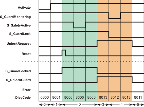
Signal sequence diagram
The diagram below shows the signal sequence of a typical application, based on the following assumptions:
S_StartReset = SAFEFALSE: Start-up inhibit after the function block has been activated and the Safety Logic Controller has started up.
S_AutoReset = SAFEFALSE: Restart inhibit after the guard locking on the closed safety equipment has been locked (i.e., once the SAFETRUE signal has returned at the S_GuardLock input).
The signal sequence diagrams in this documentation possibly omit particular diagnostic codes. For example, a diagnostic code is possibly not shown if the related function block state is a temporary transition state and only active for one cycle of the Safety Logic Controller.
Only typical input signal combinations are illustrated. Other signal combinations are possible.
|
0 |
The function block is not yet activated (Activate = FALSE). As a result, all outputs are FALSE or SAFEFALSE. |
|
1 |
Function block activated by Activate = TRUE. Even though the safety equipment is closed (S_GuardMonitoring = SAFETRUE) and locked (S_GuardLock = SAFETRUE) and the zone of operation signals the defined safe state (S_SafetyActive = SAFETRUE), the S_GuardLocked output = SAFEFALSE, as a start-up inhibit (S_StartReset = SAFEFALSE) is specified. |
|
2 |
A positive edge at the Reset input removes the start-up inhibit and the S_GuardLocked output switches to SAFETRUE. The S_GuardLocked output remains SAFETRUE, although the S_SafetyActive input is SAFEFALSE for some time (zone of operation is temporarily no longer in the defined safe state). |
|
3 |
The request to unlock the guard locking triggered by UnlockRequest = TRUE and the confirmation that the zone of operation is in the defined safe state again (S_SafetyActive = SAFETRUE) cause the S_GuardLocked output to switch to SAFEFALSE and the S_UnlockGuard output to SAFETRUE. The S_UnlockGuard output remains SAFETRUE for as long as the unlock request is present at the UnlockRequest input. |
|
4 |
The safety equipment is opened (S_GuardMonitoring and S_GuardLock both become SAFEFALSE) and closed again (S_GuardMonitoring becomes SAFETRUE again), but not locked after closing (S_GuardLock remains SAFEFALSE). Therefore, the S_GuardLocked output remains SAFEFALSE. |
|
5 |
The S_UnlockGuard output switches to SAFEFALSE, as input UnlockRequest is now also FALSE. The safety equipment is not yet locked (S_GuardLock is still SAFEFALSE). |
The other signal sequence diagram can be taken into account.
Application example: Single-channel connection of door switch and guard locking interlock
This example describes the connection of a single-channel guard with lockable guard locking to the safety-related SF_GuardLocking function block. A start-up inhibit and a restart inhibit are specified.
In this example, the arrangement of the switch meets the requirements of EN 1088, Appendix M.
The door switch and the contact for confirmation of locking have a single-channel connection to the inputs of the Safety Logic Controller. The coil for opening the interlock also has a single-channel connection to an output of the Safety Logic Controller.
The sensors/actuators are connected to the Safety Logic Controller and function block as follows:
-
The mechanically actuated position switch B1 (door switch) is connected to input terminal I0 of the safety-related input device SDI 1. Its signal is assigned to the global I/O variable B1_GMON_In and connected to the S_GuardMonitoring input of the function block.
-
The guard locking feedback signal is connected to input terminal I2 of the safety-related SDI 1 input device. Its signal is assigned to the global I/O variable K1_GLOC_In and connected to the S_GuardLock input of the function block.
-
Button S2 is connected to input terminal NI0 of the standard input device DI 1; the TRUE signal of this button triggers a request to unlock the door. The assigned global I/O variable S2_UREQ_In is connected to the UnlockRequest input of the function block.
-
Reset button S3 is connected to the input terminal NI2 of the standard input device DI 1. Its signal is assigned to the global I/O variable S3_Reset_GL and connected to the Reset input of the function block. The signal of this button is used to reset error states of the function block and to remove the start-up inhibit/restart inhibit (see below).
-
The S_UnlockGuard output signal of the function block controls the coil for opening the interlock via the connected global I/O variable K1_ULOCK_Out. This coil K1 is connected to the output terminal O0 of the Safety Logic Controller, which is in turn assigned to K1_ULOCK_Out.
S_StartReset and S_AutoReset are both switched to SAFEFALSE, in other words:
-
S_StartReset = SAFEFALSE: Start-up inhibit after the Safety Logic Controller has been started up and the function block has been activated.
-
S_AutoReset = SAFEFALSE: Restart inhibit after the SAFETRUE signal has returned at the S_GuardLock input.
The "Machine stopped"' signal is connected to input S_SafetyActive of the SF_GuardLocking function block; this signal originates from a standstill monitor, for example.
The enable output S_GuardLocked of the SF_GuardLocking function block is directly connected to a global I/O variable or to an output terminal of the application via further safety-related functions/function blocks.
Connect the S_GuardLocked enable output of the SF_GuardLocking function block to the S_OutControl input of the SF_EDM function block, for example, thus implementing a two-channel output connection.
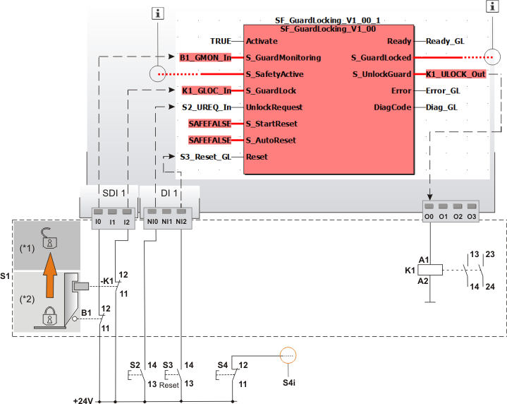
|
S1 |
Safety-related switch with guard locking, contains - Door switch (B1), single-channel - Lock monitoring of the guard locking (contact -K1) and - Coil (K1) for opening the interlock |
|
(*1) |
Guard locking of S1: open |
|
(*2) |
Guard locking of S1: closed |
|
S2 |
Request to unlock the door |
|
S3 |
Reset button for resetting errors and removing an active start-up inhibit/restart inhibit |
|
S4 |
Button for stopping the machine. |
|
S4i |
Signal for stopping the machine. |
|
|
See note above the illustration. |

Detailed information
Additional information is available in the following sections: