Connecting the Sercos Bus to the Track
Wiring Example
Also refer to Additional Wiring Example.
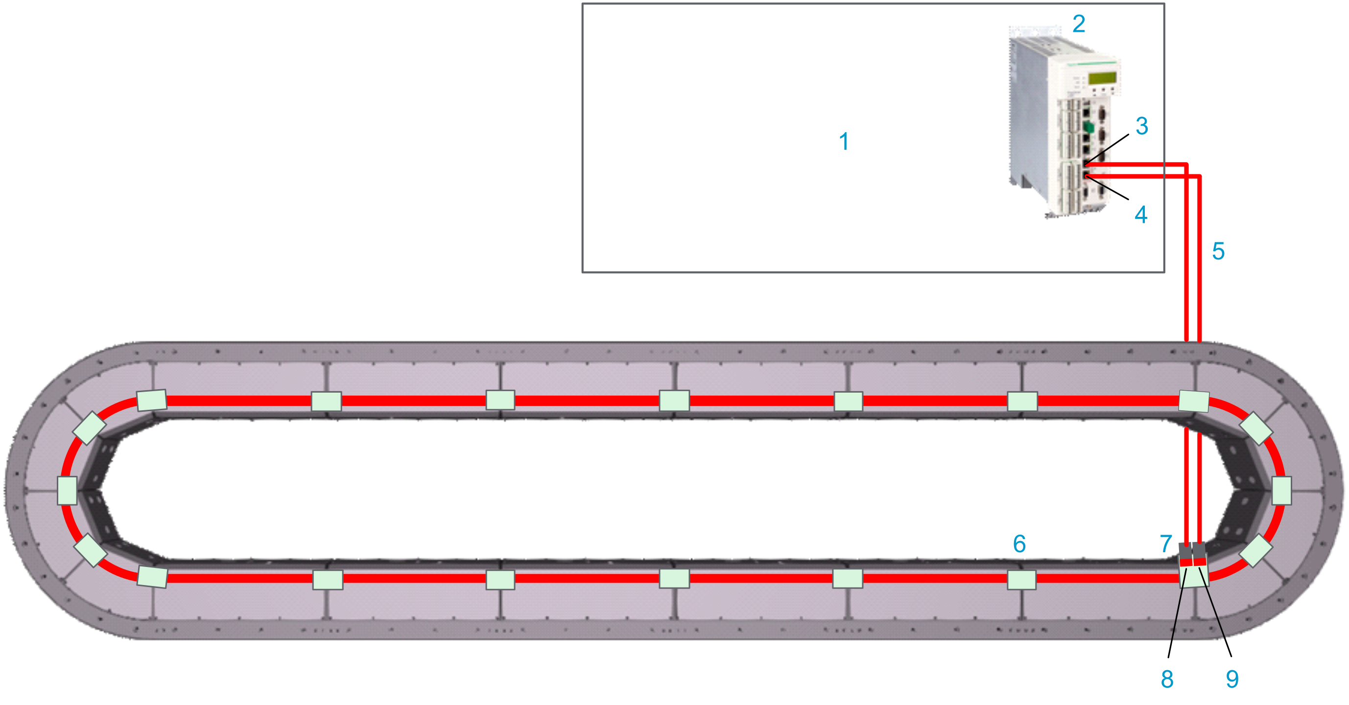
Closed track
|
Element |
Description |
|---|---|
|
1 |
Control cabinet |
|
2 |
LMC Pro2 Motion Controller |
|
3 |
Sercos port 1 (CN12) of the controller |
|
4 |
Sercos port 2 (CN13) of the controller |
|
5 |
Sercos cables |
|
6 |
Lexium™ MC communication interconnect |
|
7 |
Lexium™ MC communication interconnect with two Sercos connectors (in/out) |
|
8 |
Sercos port P1 (infeed) of a closed Lexium™ MC12 multi carrier track |
|
9 |
Sercos port P2 (outfeed) of a closed Lexium™ MC12 multi carrier track |
Description
-
The LMC Pro2 Motion Controller is installed in a cabinet.
-
The LMC Pro2 Motion Controller is connected to the Lexium™ MC12 multi carrier track with pre-assembled cables. If you do not use pre-assembled cables, make sure not to exceed a Sercos cable length of 50 m (164 ft).
-
The LMC Pro2 Motion Controller communicates with the Lexium™ MC12 multi carrier track via Sercos bus.
-
The Sercos bus
is distributed from segment to segment via the Lexium™ MC communication interconnects.
Connecting the Sercos Bus to the Lexium™ MC12 multi carrier Track
The following describes the Sercos bus connection from the LMC Pro2 Motion Controller to the Lexium™ MC12 multi carrier track:
|
Step |
Action |
|---|---|
|
1 |
Connect the Sercos cables (5) to the LMC Pro2 Motion Controller (2). |
|
2 |
Connect the Sercos cables (5) to the Lexium™ MC communication interconnect with the two Sercos connectors (7) at the top of a segment. Verify that the Lexium™ MC communication interconnect is fixed with its four corresponding screws (M3x8) to the segment, with a torque of 0.6 Nm (5.31 lbf-in). |
Pinout and Cable Diagram
Pinout
Pre-assembled Sercos cable.
Only operate the Lexium™ MC12 multi carrier with approved, specified cables, accessories and replacement equipment by Schneider Electric.
| DANGER | |
|---|---|
|
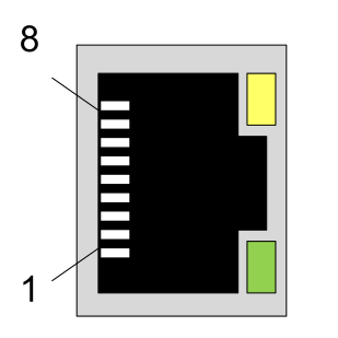
Connector at LMC Pro2 Motion Controller (RJ45, CN12/CN13) |
Pin from CN12/CN13 |
Designation |
Description |
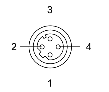
Pin from M12 connector |
Connector (M12, D-coded, socket) at the Lexium™ MC12 multi carrier track |
|---|---|---|---|---|---|
|
1 |
Tx+ |
Output transmit data + |
1 |
|
|
2 |
Tx- |
Output transmit data - |
3 |
||
|
3 |
Rx+ |
Input receive data + |
2 |
||
|
4 |
– |
Reserved |
N/A |
||
|
5 |
– |
Reserved |
N/A |
||
|
6 |
Rx- |
Input receive data - |
4 |
||
|
7 |
– |
Reserved |
N/A |
||
|
8 |
– |
Reserved |
N/A |
||
|
Cable diagram Shield connected to housing on connector side. 
|
|||||
| WARNING | |
|---|---|
Additional Wiring Example
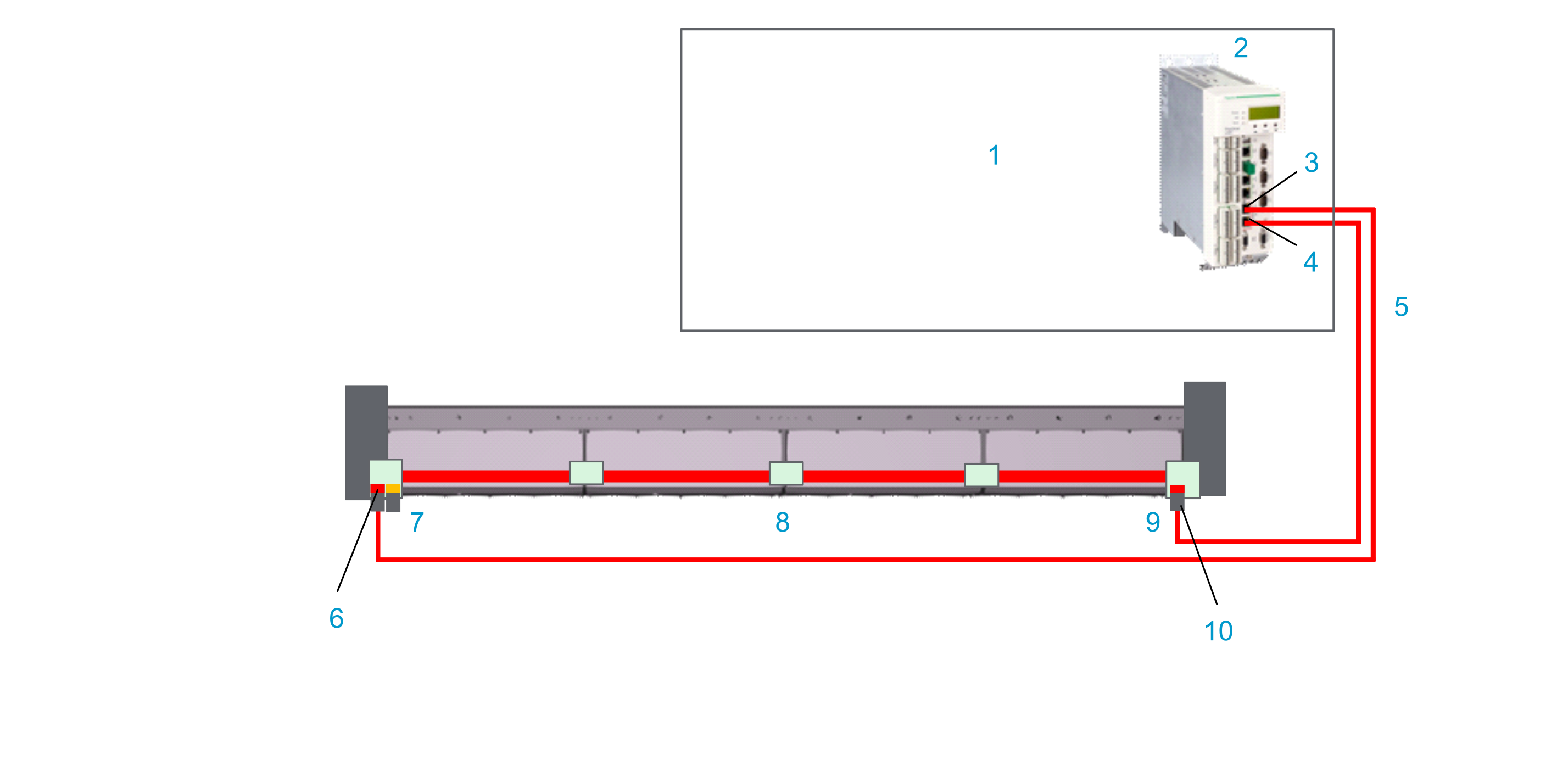
Open track
With an open track, you need a communication interconnect (7) at the beginning of the open track with one Sercos (and one SFO) connector and a communication interconnect (9) at the end of the open track with one Sercos connector.
Also refer to Open Track.
|
Element |
Description |
|---|---|
|
1 |
Control cabinet |
|
2 |
LMC Pro2 Motion Controller |
|
3 |
Sercos port P1 (CN12) of the controller |
|
4 |
Sercos port P2 (CN13) of the controller |
|
5 |
Sercos cables |
|
6 |
Sercos port P1 (infeed) of an open Lexium™ MC12 multi carrier track |
|
7 |
Lexium™ MC communication interconnect with one Sercos (and one SFO) connector. |
|
8 |
Lexium™ MC communication interconnect |
|
9 |
Lexium™ MC communication interconnect with one Sercos connector. |
|
10 |
Sercos port P2 (outfeed) of an open Lexium™ MC12 multi carrier track |