SF_EnableSwitch_SE
The following description is valid for the function block SF_EnableSwitch_SE_V1_0z, Version 1.0z (where z = 0 to 9).
Short description
|
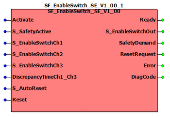
The safety-related SF_EnableSwitch_SE function block evaluates the signals of a manually actuated three-stage enable switch (in accordance with EN 60204) in order to identify its switching stage and direction. The connected enable switch can be used to remove safeguarding, provided that the appropriate operating mode (e.g., limitation of the speed or range of motion) is selected and active. A restart inhibit can be specified via S_AutoReset. |
|
The SF_EnableSwitch_SE function block supports the Schneider Electric enable switch types "Preventa XY2 XY2AU1" and "Preventa XY2 XY2AU2". The function block evaluates 3 input signals (while the PLCopen SF_EnableSwitch function block evaluates two input signals). The function block additionally monitors signal equivalence at its inputs S_EnableSwitchCh1 and S_EnableSwitchCh3.
For details and technical specification of the Preventa enable switches refer to the respective Instruction Sheet.
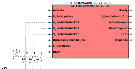
Connection and switching diagram
Connect the signals of the enable switch connected to the Safety Logic Controller to the inputs of the safety-related SF_EnableSwitch_SE function block as follows:
|
|
Pressure point |
|
|
Forcibly guided contacts (The auxiliary contact of the enable switch type "Preventa XY2 XY2AU2" is not considered in the figure.) |
Connect the signal from N/O contact E1 of the enable switch to function block input S_EnableSwitchCh1. Connect the signal from N/C contact E3 to function block input S_EnableSwitchCh2 and the signal from N/O contact E2 to input S_EnableSwitchCh3.
Note that the function block monitors signal equivalence at its inputs S_EnableSwitchCh1 and S_EnableSwitchCh3. Therefore the same contact type must be connected to these inputs.
By means of the defined signal sequence of the contacts, the safety-related function block can detect the switching stage and the switching direction of the enable switch (switching stage 0 => switching stage 1/switching stage 2 => switching stage 0).
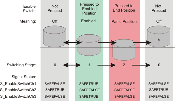
The switching sequence of the Schneider Electric enable switch types "Preventa XY2 XY2AU1" and "Preventa XY2 XY2AU2" is shown in the figure below. This sequence results in the signals also shown in the graphic at function block inputs S_EnableSwitchCh1, S_EnableSwitchCh2 and S_EnableSwitchCh3.
The error state of the function block can only be exited if the cause of the error no longer exists. To leave the error state, release the enable switch to move it to switching stage 0. If a restart inhibit has been set with S_AutoReset = SAFEFALSE, it must then be removed by pressing the reset button.
Filter times of the input channels
If the parameterized filter time values FilterOn and FilterOff for the three input channels of the safety-related digital input module are too short, the function block may miss switching operations of the enable switch device. The function block then detects a plausibility error and enters the error state C030. (Refer to the topic "Diagnostic Codes" for details.)
Proceed as follows to set the FilterOn and FilterOff values:
-
In EcoStruxure Machine Expert - Safety, open the Bus Navigator and select the digital input module involved in the Devices tree on the left. The parameters are visible and can be edited in the grids on the right.
-
Locate the parameter group if each digital input channel involved and set suitable values for the parameters FilterOff and FilterOn.
A practical value for the supported switch types Preventa XY2 XY2AU1 and XY2 XY2AU2 is 50 ms.
For detailed information, refer to the Safety Modules Parameters guide and open the corresponding chapter of the module used.
The set filter time for the input channels may have an impact on the safety response time of your application.
| WARNING | |
|---|---|
Function block inputs
Click the corresponding hyperlinks to obtain detailed information on the items below.
|
Name |
Short description |
Value |
|---|---|---|
|
State-controlled input for activating the function block. Data type: BOOL Initial value: FALSE |
|
|
|
State-controlled signal input for setting the selected operating mode to active (feedback signal, e.g., from safety-related SF_ModeSelector function block). Data type: SAFEBOOL Initial value: SAFEFALSE |
|
|
|
Input for the signal from N/O contact E1 of the connected enable switch. Data type: SAFEBOOL Initial value: SAFEFALSE The function block monitors equivalence of this input with input S_EnableSwitchCh3. The allowed discrepancy time is set at input DiscrepancyTimeCh1_Ch3. |
Possible values are: SAFETRUE or SAFEFALSE, depending on the switching stage (see diagram). |
|
|
Input for the signal from N/C contact E3 of the connected enable switch. Data type: SAFEBOOL Initial value: SAFEFALSE |
Possible values are: SAFETRUE or SAFEFALSE, depending on the switching stage (see diagram). |
|
|
Input for the signal from N/O contact E2 of the connected enable switch. Data type: SAFEBOOL Initial value: SAFEFALSE The function block monitors equivalence of this input with input S_EnableSwitchCh1. The allowed discrepancy time is set at input DiscrepancyTimeCh1_Ch3. |
Possible values are: SAFETRUE or SAFEFALSE, depending on the switching stage (see diagram). |
|
|
Input for specifying the maximum permissible discrepancy time in milliseconds. During this discrepancy time, the signals at S_EnableSwitchCh1 and S_EnableSwitchCh3 may be different. However, after the discrepancy time has elapsed, the inputs must be equal to each other or an error is detected (output Error = TRUE, output S_EnableSwitchOut = SAFEFALSE). Data type: TIME Initial value: #0ms |
Enter a time value according to your risk analysis. Refer to the third hazard message below this table. |
|
|
State-controlled input for specifying the restart inhibit after the connected enable switch has applied a valid signal sequence/combination at inputs S_EnableSwitchCh1, S_EnableSwitchCh2 and S_EnableSwitchCh3. An active restart inhibit must be removed manually by a positive signal edge at the Reset input. A deactivated restart inhibit causes the S_EnableSwitchOut output to switch to SAFETRUE automatically when the function block is activated and the safety-related function is no longer requested. Refer to the first hazard message below this table. Data type: SAFEBOOL Initial value: SAFEFALSE |
|
|
|
Edge-triggered input for the reset signal:
Refer to the second hazard message below this table. Data type: BOOL Initial value: FALSE
NOTE:
Resetting does not occur with a negative (falling) edge, as specified by the EN ISO 13849-1 standard, but with a positive (rising) edge. |
|
| WARNING | |
|---|---|
Resetting the function block by means of a positive signal edge at the Reset input can cause the S_EnableSwitchOut output to switch to SAFETRUE immediately (depending on the status of the other inputs).
| WARNING | |
|---|---|
| WARNING | |
|---|---|
Function block outputs
Click the corresponding hyperlinks to obtain detailed information on the items below.
|
Name |
Short description |
Value |
|---|---|---|
|
Output for signaling "Function block activated/not activated". Data type: BOOL |
|
|
|
Output for enable signal of the function block. Data type: SAFEBOOL |
|
|
|
Output for signaling "safety-related function requested". This output displays whether the safety chain is interrupted and as a result, the attention of the operator is required. Data type: BOOL |
|
|
|
Output for signaling "reset is required". This output indicates whether a reset by the operator is required. Data type: BOOL |
|
|
|
Output for error message. Data type: BOOL Refer to the hazard message below this table. |
|
|
|
Output for diagnostic message. Data type: WORD |
Diagnostic message of the function block. The possible values are listed and described in the topic "Diagnostic codes". |
If you have not activated a restart inhibit (S_AutoReset = SAFETRUE), a manual reset does not have to be performed following error removal. In such cases, the error message is confirmed automatically once the error is removed.
| WARNING | |
|---|---|
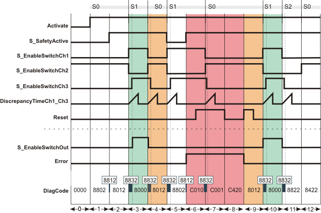
Signal sequence diagram
This diagram shows the signal curve for a typical application with a set restart inhibit after an invalid signal sequence/combination (S_AutoReset = SAFEFALSE).
The signal sequence diagrams in this documentation possibly omit particular diagnostic codes. For example, a diagnostic code is possibly not shown if the related function block state is a temporary transition state and only active for one cycle of the Safety Logic Controller.
Only typical input signal combinations are illustrated. Other signal combinations are possible.
|
0 |
The function block is not yet activated (Activate = FALSE). As a result, all outputs are FALSE or SAFEFALSE. |
|
1 |
The function block is activated (Activate = TRUE). Switching stage 0 (S0 in the figure) is present (input S_EnableSwitchCh1 and S_EnableSwitchCh3 = SAFEFALSE, input S_EnableSwitchCh2 = SAFETRUE). The operating mode is not active (S_SafetyActive = SAFEFALSE). The S_EnableSwitchOut output remains in the defined safe state (SAFEFALSE). |
|
2 |
The operating mode is signaled via the feedback signal S_SafetyActive = SAFETRUE. |
|
3 |
Change from switching stage 0 to switching stage 1 (S1 in the figure): S_EnableSwitchCh1 switches to SAFETRUE and S_EnableSwitchCh2 becomes SAFEFALSE. S_EnableSwitchCh3 follows S_EnableSwitchCh1 within the time period set at DiscrepancyTimeCh1_Ch3. All relevant conditions are fulfilled, S_EnableSwitchOut output becomes SAFETRUE. |
|
4 |
Change from switching stage 1 back to switching stage 0: S_EnableSwitchCh1 becomes SAFEFALSE, S_EnableSwitchCh2 becomes SAFETRUE and S_EnableSwitchCh3 follows S_EnableSwitchCh1 within the time period set at DiscrepancyTimeCh1_Ch3. As a result the S_EnableSwitchOut output becomes SAFEFALSE. |
|
5 |
Change from switching stage 0 to switching stage 1: S_EnableSwitchCh1 switches to SAFETRUE and S_EnableSwitchCh2 becomes SAFEFALSE. S_EnableSwitchCh3 follows S_EnableSwitchCh1 within the time period set at DiscrepancyTimeCh1_Ch3. However, as the operating mode is no longer active (S_SafetyActive = SAFEFALSE), the S_EnableSwitchOut output remains SAFEFALSE. |
|
6 |
The operating mode is now active again and the function block initially expects switching stage 0. However, as switching stage 1 is present at this time (S_EnableSwitchCh1 and S_EnableSwitchCh3 = SAFETRUE and S_EnableSwitchCh2 = SAFEFALSE), the Error output becomes TRUE. The positive edge at the Reset input is ignored, as the impermissible switching stage 1 is still present (S_EnableSwitchCh1 and S_EnableSwitchCh3 = SAFETRUE and S_EnableSwitchCh2 = SAFEFALSE). |
|
7 |
Change to valid switching stage 0. However, the function block detects a static TRUE signal at the Reset input, so the Error output remains TRUE. |
|
8 |
While the valid switching stage 0 is present (S_EnableSwitchCh1 and S_EnableSwitchCh3 = SAFEFALSE and S_EnableSwitchCh2 = SAFETRUE), the static signal disappears from the Reset input. However, the error state (Error = TRUE) then has to be reset by a positive edge at the Reset input. |
|
9 |
The positive edge at the Reset input resets the Error output to FALSE and removes the restart inhibit. |
|
10 |
Change from switching stage 0 to switching stage 1 (S_EnableSwitchCh1 switches to SAFETRUE, S_EnableSwitchCh2 becomes SAFEFALSE, S_EnableSwitchCh3 follows S_EnableSwitchCh1 within DiscrepancyTimeCh1_Ch3), the S_EnableSwitchOut output becomes SAFETRUE. |
|
11 |
Change from switching stage 1 to switching stage 2 (S_EnableSwitchCh1, S_EnableSwitchCh2 and S_EnableSwitchCh3 = SAFEFALSE), the S_EnableSwitchOut output is SAFEFALSE. |
|
12 |
From stage 2 a transition is only possible to stage 0: By releasing the button of the enable switch device, input S_EnableSwitchCh1 and S_EnableSwitchCh3 switch to SAFEFALSE (DiscrepancyTimeCh1_Ch3 is not exceeded) and input S_EnableSwitchCh2 becomes SAFETRUE. S_EnableSwitchOut output remains SAFEFALSE. |
The other signal sequence diagram can be taken into account.
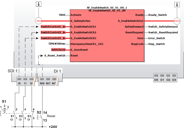
Application example
This example illustrates the typical connection of a three-stage enable switch S1 to the safety-related SF_EnableSwitch_SE function block. The three signals from the enable switch are connected to input terminals I0, I1 and I2 of the safety-related input device SDI 1.
-
The signal from the N/O contact E1 of the enable switch device (input terminal I0 of the safety-related input device SDI 1) is assigned to the global I/O variable SwitchControl1_In. This global I/O variable is connected to the S_EnableSwitchCh1 input of the function block for evaluation.
-
The signal from the other N/O contact E2 (input terminal I1 of SDI 1) is assigned to the global I/O variable SwitchControl3_In. This global I/O variable is connected to the S_EnableSwitchCh3 input of the function block because the function block monitors the signal equivalence of this input with input S_EnableSwitchCh1.
-
The signal of the N/C contact E3 (input terminal I2 of SDI 1) is assigned to the global I/O variable SwitchControl2_In. This global I/O variable is connected to the S_EnableSwitchCh2 input of the function block for evaluation.
The function block is perpetually activated by the TRUE constant at the Activate input.
A restart inhibit is set via S_AutoReset. This inhibit becomes active after a valid signal combination returns at the function block inputs S_EnableSwitchCh1, S_EnableSwitchCh2 and S_EnableSwitchCh3. The Reset button S2 for removing the restart inhibit is connected to input terminal NI0 of the standard input device DI 1.
In the example, the enable signal at the S_EnableSwitchOut output controls the removal of safeguarding. To this end, the S_EnableSwitchOut enable output is connected to other safety-related function blocks or functions.
|
S2 |
Reset |
|
|
See second note above the illustration. |

The second application example can be taken into account.
Detailed information
Additional information is available in the following sections