Electrical Connections for the Lexium 62 Servo Drives
Electrical Connections for the Lexium 62 Variants C, D, E, F
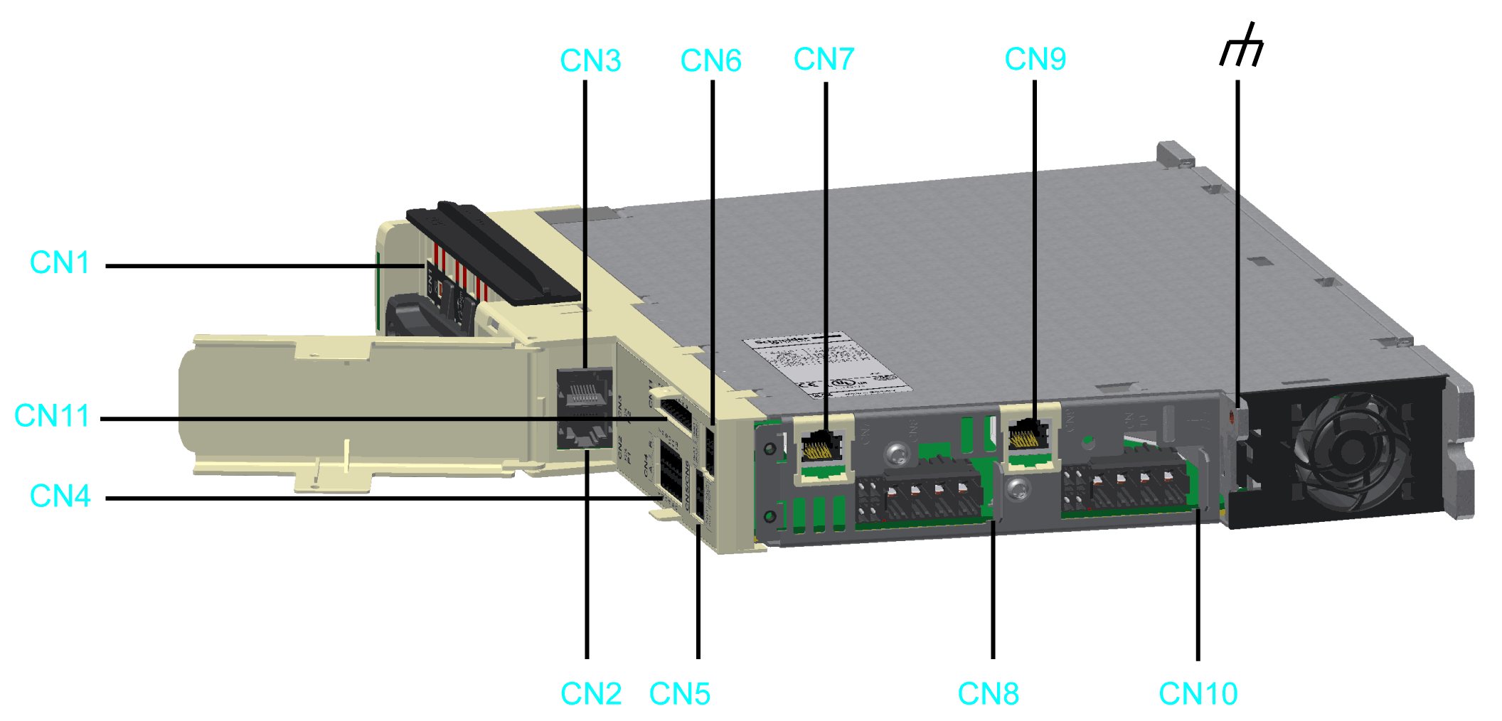
|
Connector |
Description |
Connection cross-section [mm2] / [AWG] |
Tightening torque [Nm] / [lbf in] |
|---|---|---|---|
|
Bus Bar Module |
– |
2.5 / 22.13 |
|
|
Sercos |
– |
– |
|
|
Digital inputs/outputs |
0.25...1.5 / 24...16 |
– |
|
|
24 V supply for digital inputs/outputs |
0.25...1.5 / 24...16 |
– |
|
|
Inverter Enable 1-channel(1) |
0.2...1.5 / 24...16 |
– |
|
|
Encoder connector CN7 - axis A CN9 - axis B (only for double drives) |
– |
– |
|
|
Motor phases - axis A |
0.2...6 / 24...10 |
– |
|
|
Motor phases - axis B (only for double drives; variants D, F) |
|||
|
Inverter Enable 2-channel |
0.2 - 1.5 / 24 - 16 |
– |
|
|
Functional ground (earth) |
Mounting point for the shield(2) |
3.5 / 30.98 |
|
|
(1) Valid only for Lexium 62 variants C/D, refer to Extended Safety-Related Functions - Inverter Enable via Hardware Input (2) Refer to External Shield Connection on the Drive Module (LMX62DU and LMX62DD) |
|||
Electrical Connections for the Lexium 62 Variant G
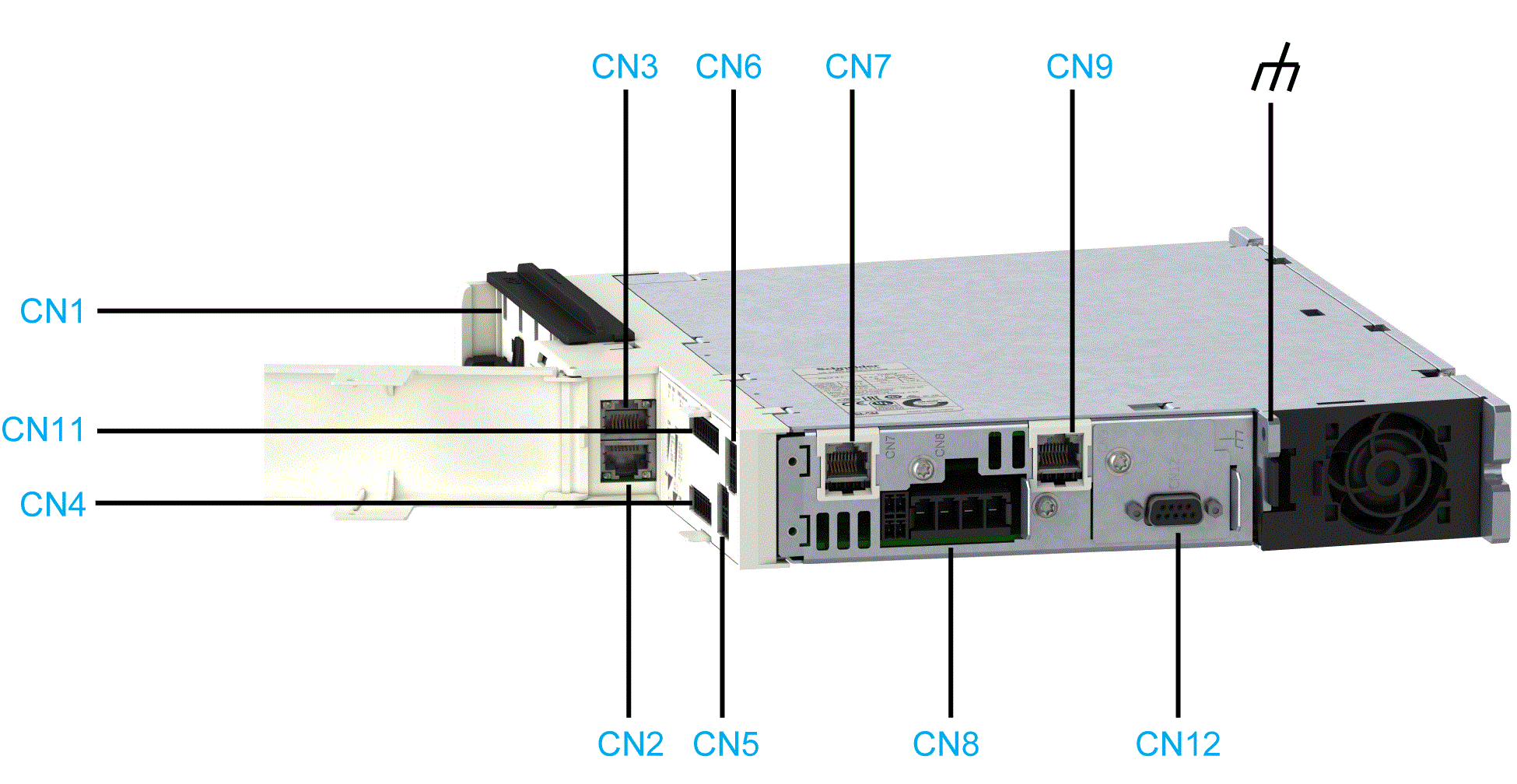
|
Connector |
Description |
Connection cross-section [mm2] / [AWG] |
Tightening torque [Nm] / [lbf in] |
|---|---|---|---|
|
Bus Bar Module |
– |
2.5 / 22.13 |
|
|
Sercos |
– |
– |
|
|
Digital inputs/outputs |
0.25...1.5 / 24...16 |
– |
|
|
24 V supply for digital inputs/outputs |
0.25...1.5 / 24...16 |
– |
|
|
Inverter Enable 1-channel |
0.2...1.5 / 24...16 |
– |
|
|
CN7 - Encoder connector CN9 - Additional machine encoder input |
– |
– |
|
|
Motor phases - axis A |
0.2...6 / 24...10 |
– |
|
|
Inverter Enable 2-channel |
0.2 - 1.5 / 24 - 16 |
– |
|
|
Machine Encoder Output |
0.2...6 / 24...10 |
– |
|
|
Functional ground (earth) |
Mounting point for the shield(1) |
3.5 / 30.98 |
|
Electrical Connections for the Single Drive LXM62DC13
|
LXM62DC13 variant C/E |
LXM62DC13 variant G |
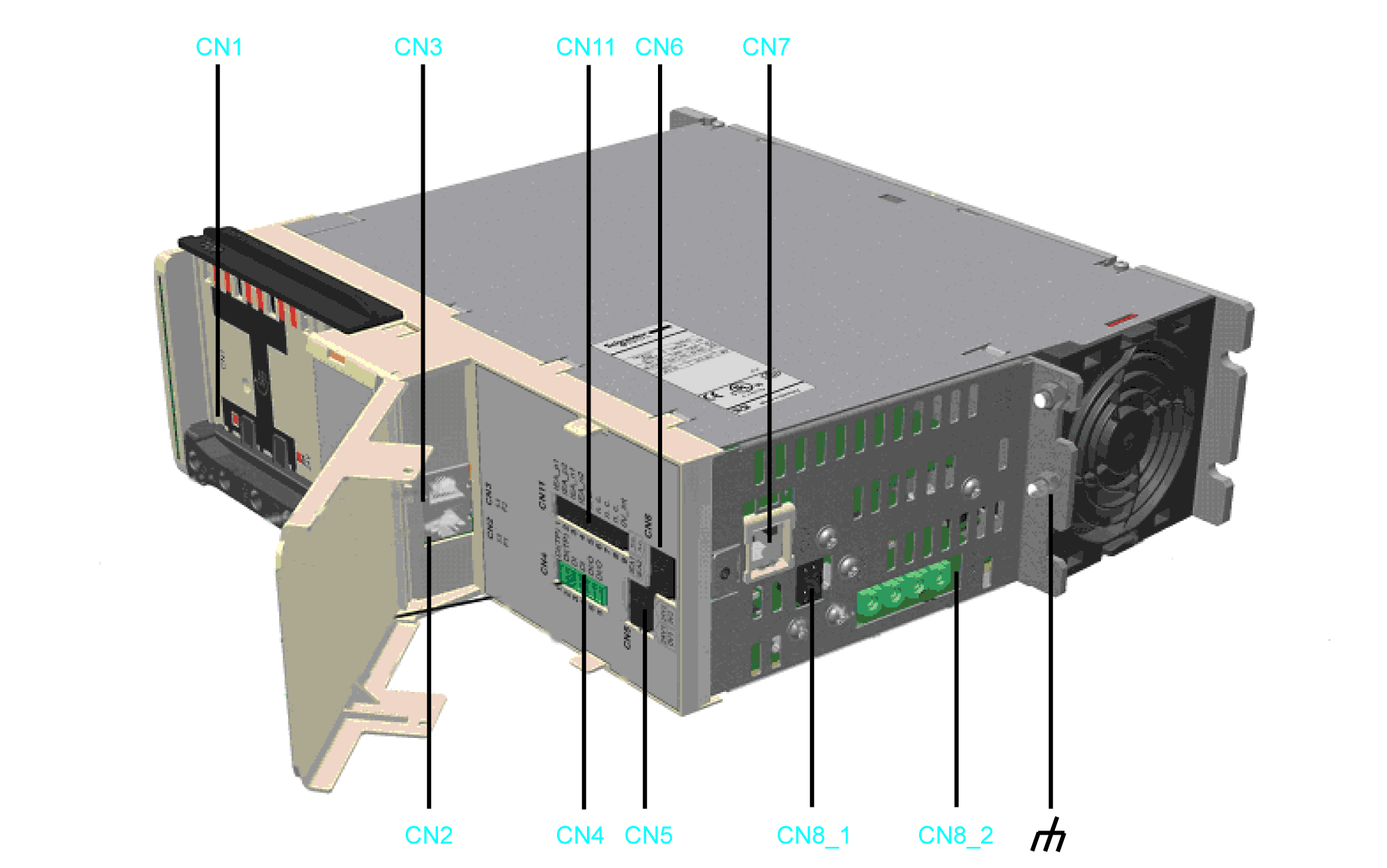
|
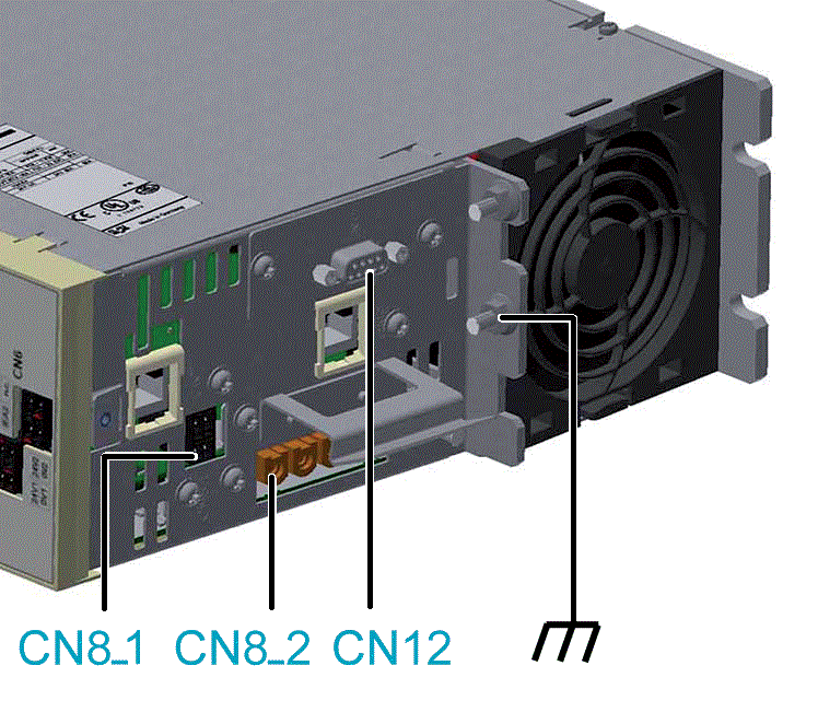
|
|
Connector |
Description |
Connection cross-section [mm2] / [AWG] |
Tightening torque [Nm] / [lbf in] |
|---|---|---|---|
|
Bus Bar Module |
– |
2.5 / 22.13 |
|
|
Sercos |
– |
– |
|
|
Digital inputs/outputs |
0.25...1.5 / 24...16 |
– |
|
|
24 V supply for digital inputs/outputs |
0.25...1.5 / 24...16 |
– |
|
|
Inverter Enable 1-channel(1) |
0.2...1.5 / 24...16 |
– |
|
|
Encoder connector |
– |
– |
|
|
Motor temperature / holding brake |
0.2...1.5 / 24...16 |
– |
|
|
Motor phases |
4...6 / 12...10 |
– |
|
|
Inverter Enable 2-channel |
0.2 - 1.5 / 24 - 16 |
– |
|
|
Machine Encoder Output (only for LXM62DC13G) |
0.2...6 / 24...10 |
– |
|
|
Functional ground (earth) |
Mounting point for the shield(2) |
3.5 / 30.98 |
|
|
(1) Valid only for Lexium 62 variants C/G, refer to Extended Safety-Related Functions - Inverter Enable via Hardware Input (2) Refer to External Shield Connection on the Drive Module LXM62DC13. |
|||
Removable Spring-Clamping Terminal Block Wiring
The details in the following table apply for the wiring on the removable spring-clamping terminal block of the CN4, CN5, CN6, CN8 / CN10 (holding brake, temperature) and CN11 connections.
Overview of the connection cross-sections for the removable spring-clamping terminal blocks CN4, CN5, CN6, CN8 / CN10 (holding brake, temperature) and CN11:
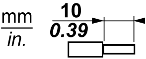
|
Rigid wire 
|
Flexible wire 
|
Flexible wire with a wire end sleeve without a plastic sleeve 
|
Flexible wire with a wire end sleeve and plastic sleeve 
|
|---|---|---|---|---|
|
mm2 |
0.2...1.5 |
0.2...1.5 |
0.25...1.5 |
0.25...0.75 |
|
AWG |
24...16 |
24...16 |
23...16 |
23...19 |
The details in the following table apply for the wiring on the removable spring-clamping terminal blocks of the connections CN8 / CN10 (PE, U, V, W).
Overview of the connection cross-sections for the removable spring-clamping terminal blocks CN8 / CN10 motor phases (PE, U, V, W):
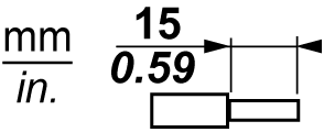
|
Rigid wire 
|
Flexible wire 
|
Flexible wire with a wire end sleeve without a plastic sleeve 
|
Flexible wire with a wire end sleeve and plastic sleeve 
|
|---|---|---|---|---|
|
mm2 |
0.2...10 |
0.2...6 0.2...10(1) |
0.25...6 |
0.25...4 |
|
AWG |
24...8 |
24...10 24...8(1) |
23...10 |
23...12 |
|
(1) Flexible conductors with an outside diameter of ≤ 4 mm |
||||
CN1 - Bus Bar Module
The DC bus voltage and the 24 Vdc control voltage are distributed and the protective conductor is connected via the Bus Bar Module.

|
Pin |
Designation |
Description |
|---|---|---|
|
1 |

|
Protective ground (earth) |
|
2 |
DC- |
DC bus voltage - |
|
3 |
DC+ |
DC bus voltage + |
|
4 |
24 V |
Supply voltage + |
|
5 |
0 V |
Supply voltage - |
CN2/3 - Sercos
The Sercos connection is used for the communication between the controller and the drive.
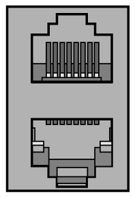
|
Pin |
Designation |
Description |
|---|---|---|
|
1.1 |
Eth0_Tx+ |
Positive transmission signal |
|
1.2 |
Eth0_Tx- |
Negative transmission signal |
|
1.3 |
Eth0_Rx+ |
Positive receiver signal |
|
1.4 |
N.C. |
Reserved |
|
1.5 |
N.C. |
Reserved |
|
1.6 |
Eth0_Rx- |
Negative receiver signal |
|
1.7 |
N.C. |
Reserved |
|
1.8 |
N.C. |
Reserved |
|
2.1 |
Eth1_Tx+ |
Positive transmission signal |
|
2.2 |
Eth1_Tx- |
Negative transmission signal |
|
2.3 |
Eth1_Rx+ |
Positive receiver signal |
|
2.4 |
N.C. |
Reserved |
|
2.5 |
N.C. |
Reserved |
|
2.6 |
Eth1_Rx- |
Negative receiver signal |
|
2.7 |
N.C. |
Reserved |
|
2.8 |
N.C. |
Reserved |
CN4 - Digital Inputs / Outputs
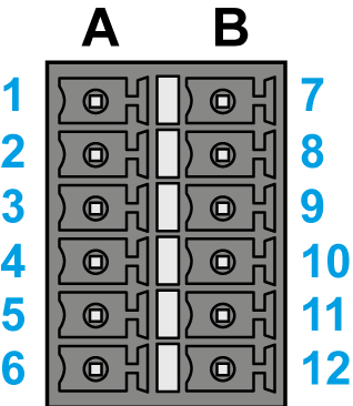
The connection CN4 provides several digital inputs and outputs on the drive:
-
The digital inputs A_DI1 / A_DI2 (Single Drive) or A_DI1, A_DI2 / B_DI1, B_DI2 (Double Drive) can be configured as digital inputs or as Touchprobe inputs via the EcoStruxure Machine Expert Logic Builder.
-
The digital inputs A_DI5 /A_DI6 (Single Drive) or A_DI5, A_DI6 / B_DI5, B_DI6 can be configured as digital inputs or as digital outputs via the EcoStruxure Machine Expert Logic Builder.
-
The filter time constant of the digital inputs can be set to 1 ms or 5 ms.
-
The filter time constant of the Touchprobe inputs is fixed at 100 µs.
|
Single Drive |
Double Drive |
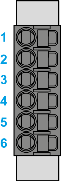
|
|
|
Pin |
Designation |
Description |
|---|---|---|
|
1 |
A_DI0 |
Axis A – Digital input 0 - Touchprobe |
|
2 |
A_DI1 |
Axis A – Digital input 1 - Touchprobe |
|
3 |
A_DI2 |
Axis A – Digital input 2 |
|
4 |
A_DI3 |
Axis A – Digital input 3 |
|
5 |
A_DI4 |
Axis A – Digital input / output 4 |
|
6 |
A_DI5 |
Axis A – Digital input / output 5 |
|
7 |
B_DI0 |
Axis B – Digital input 0 - Touchprobe (only Double Drive) |
|
8 |
B_DI1 |
Axis B – Digital input 1 - Touchprobe (only Double Drive) |
|
9 |
B_DI2 |
Axis B – Digital input 2 (only Double Drive) |
|
10 |
B_DI3 |
Axis B – Digital input 3 (only Double Drive) |
|
11 |
B_DI4 |
Axis B – Digital input/output 4 (only Double Drive) |
|
12 |
B_DI5 |
Axis B – Digital input/output 5 (only Double Drive) |
CN5 - 24 V
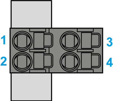
The 24 V DIO supply connector supplies the digital inputs/outputs of the drives with the required energy. The connection 0V1 is internally connected to 0V2 and the connection 24V1 is internally connected to 24V2 electrically.
|
Pin |
Designation |
Description |
|---|---|---|
|
1 |
24V1 |
Digital I/O supply voltage Axis A |
|
2 |
0V1 |
|
|
3 |
24V2 |
Digital I/O supply voltage Axis B |
|
4 |
0V2 |
-
Continuous current carrying capacity of the plug-in connectors: 3 A
-
Maximum current carrying capacity of the plug-in connectors: 4 A, 1 s
The number of the devices that can be connected depends on the application.
CN6 - Inverter Enable 1–Channel
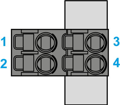
The Inverter Enable signal supplies the gate driver with voltage. In this way, the STO (Safe Torque Off) requirements according to EN 61508 and ISO 13849-1 are met. IEA1 is internally connected with IEA2 electrically, and IEB1 is internally connected with IEB2 electrically.
The single channel Inverter Enable is valid only for Lexium 62 variants C/D/G, refer to Extended Safety-Related Functions - Inverter Enable via Hardware Input.
| DANGER | |
|---|---|
|
CN6 - Inverter Enable 1–Channel |
(CN6/CN11 - Inverter Enable) |
|---|---|
|
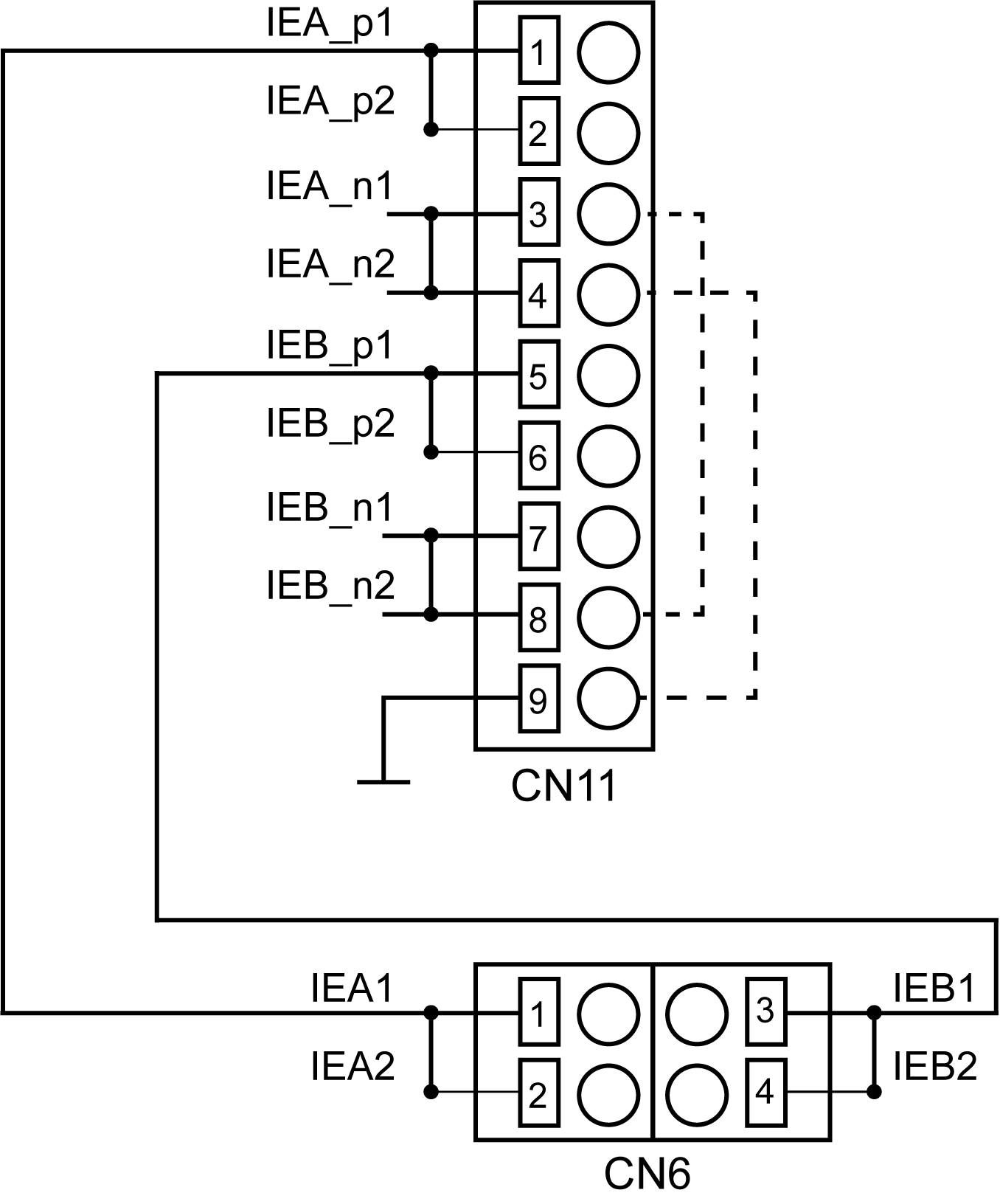
— Internal connections between CN6 and CN11 - - - Possible connection to use the two-channel Inverter Enable as a single-channel Inverter Enable The single channel Inverter Enable is valid only for Lexium 62 variants C/D/G, refer to Extended Safety-Related Functions - Inverter Enable via Hardware Input. |
|
Pin |
Designation |
Description |
|---|---|---|
|
1 |
IEA1 |
Inverter Enable signal for axis A (with CN11 PIN 1, CN11 PIN 2 and CN6 PIN 2 jumpered) |
|
2 |
IEA2 |
Inverter Enable signal for axis A (with CN11 PIN 2, CN11 PIN 1 and CN6 PIN 2 jumpered) |
|
3 |
IEB1 |
Inverter Enable signal for axis B (with CN11 PIN 5, CN11 PIN 6 and CN6 PIN 4 jumpered) |
|
4 |
IEB2 |
Inverter Enable signal for axis B (with CN11 PIN 6, CN11 PIN 5 and CN6 PIN 3 jumpered) |
-
Continuous current carrying capacity of the plug-in connectors: 3 A
-
Maximum current carrying capacity of the plug-in connectors: 4 A, 1 s
-
Maximum consumption per drive: 30 mA
The number of the devices that can be connected depends on the application.
CN7 / CN9 - Encoder Connector
The Hiperface connection consists of a standard, differential, digital connection (RS-485 = 2 wires), a differential, analog connection (sine- and cosine signal = 4 wires), and a mains connection to supply the encoder (+10 V, GND = 2 wires).
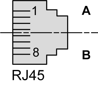
|
Pin |
Designation |
Description |
|---|---|---|
|
1 |
Cos |
Cosine track axis A/B |
|
2 |
RefCos |
Reference signal cosine axis A/B |
|
3 |
Sin |
Sine track axis A/B |
|
4 |
RS485+ |
Positive RS-485 signal axis A/B |
|
5 |
RS485- |
Negative RS-485 signal axis A/B |
|
6 |
RefSin |
Reference signal Sine axis A/B |
|
7 |
N.C. |
Reserved |
|
8 |
N.C. |
Reserved |
|
A |
P10V |
Supply voltage encoder A/B |
|
B |
GND |
0 V A/B return |
CN8 / CN10 - Motor Connection
The motor signals U, V, and W supply the motor with the required energy. The temperature signals are connected to a temperature sensor to measure the temperature of the motor. The holding brake output supplies the holding brake in the motor with the required energy.
|
Lexium 62 Drives except DC13 |
Lexium 62 DC13 Drives |
|
CN8 / CN10 - motor connector 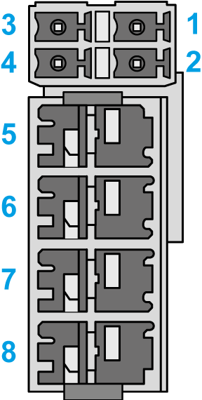
|
CN8_1 - motor temperature and holding brake 
CN8_2 - motor phases 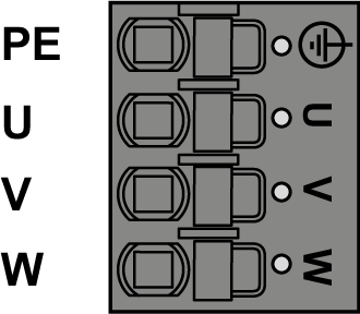
|
|
Pin |
Designation |
Description |
|---|---|---|
|
1 |
ϑ− |
Temperature negative signal |
|
2 |
ϑ+ |
Temperature positive signal |
|
3 |
BR- |
Brake negative signal |
|
4 |
BR+ |
Brake positive signal |
|
5 |
PE |
Protective Earth (ground) |
|
6 |
U |
Motor phase U |
|
7 |
V |
Motor phase V |
|
8 |
W |
Motor phase W |
|
Motor cable(1) |
Motor connectors |
Description |
|
|---|---|---|---|
|
Label of cable core |
Color of cable core |
Label |
|
|
1 |
Black |
U |
Motor phase U - Axis A/B |
|
2 |
Black |
V |
Motor phase V - Axis A/B |
|
3 |
Black |
W |
Motor phase W - Axis A/B |
|
– |
Green/Yellow |
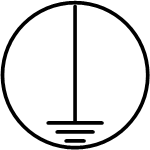
|
Protective ground (earth) - Axis A/B |
|
5 |
Black |
ϑ− |
Temperature negative signal - Axis A/B |
|
6 |
Black |
ϑ+ |
Temperature positive signal - Axis A/B |
|
7 |
Black |
BR- |
Holding brake negative signal - Axis A/B |
|
8 |
Black |
BR+ |
Holding brake positive signal - Axis A/B |
|
(1) Order numbers: VW3E1143Rxxx, VW3E1144Rxxx, VW3E1145Rxxx |
|||
The insulation-stripped length of the wires of the motor connector is 15 mm (0.59 in.). The maximum length of the motor supply cable is 75 m (246.06 ft).
CN11 - Inverter Enable 2-Channel
|
CN11 - Inverter Enable 2-Channel |
(CN6/CN11 - Inverter Enable) |
|---|---|

|

— Internal connections between CN6 and CN11 - - - Possible connection to use the two-channel Inverter Enable as a single-channel Inverter Enable The single channel Inverter Enable is valid only for Lexium 62 variants C/D/G, refer to Extended Safety-Related Functions - Inverter Enable via Hardware Input. |
|
Pin |
Designation |
Description |
|---|---|---|
|
1 |
IEA_p1 |
Inverter Enable signal for drive A 24 V (with CN6 PIN 1, CN6 PIN 2 and CN11 PIN 2 jumpered) |
|
2 |
IEA_p2 |
Inverter Enable signal for drive A 24 V (with CN6 PIN 1, CN6 PIN 2 and CN11 PIN 1 jumpered) |
|
3 |
IEA_n1 |
Inverter Enable signal for drive A 0 V external |
|
4 |
IEA_n2 |
Inverter Enable signal for drive A 0 V external |
|
5 |
IEB_p1 |
Inverter Enable signal for drive B 24 V (with CN6 PIN 3, C6 PIN 4 and CN11 PIN 6 jumpered) |
|
6 |
IEB_p2 |
Inverter Enable signal for drive B 24 V (with CN6 PIN 4, C6 PIN 3 and CN11 PIN 5 jumpered) |
|
7 |
IEB_n1 |
Inverter Enable signal for drive B 0 V external |
|
8 |
IEB_n2 |
Inverter Enable signal for drive B 0 V external |
|
9 |
0V_int |
Inverter Enable signal 0 V internal |
CN12 - Encoder Output Simulation
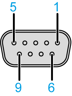
|
Pin |
Designation |
Description |
|---|---|---|
|
1 |
B- |
Encoder Output track B / Differential - |
|
2 |
B+ |
Encoder Output track B / Differential + |
|
3 |
A+ |
Encoder Output track A / Differential + |
|
4 |
A- |
Encoder Output track A / Differential - |
|
5 |
n.c. |
- |
|
6 |
n.c. |
- |
|
7 |
Z+ |
Encoder Output track B / Differential + |
|
8 |
Z- |
Encoder Output track B / Differential - |
|
9 |
GND_EXT |
External Ground |
