Electrical Connections and Dimensions
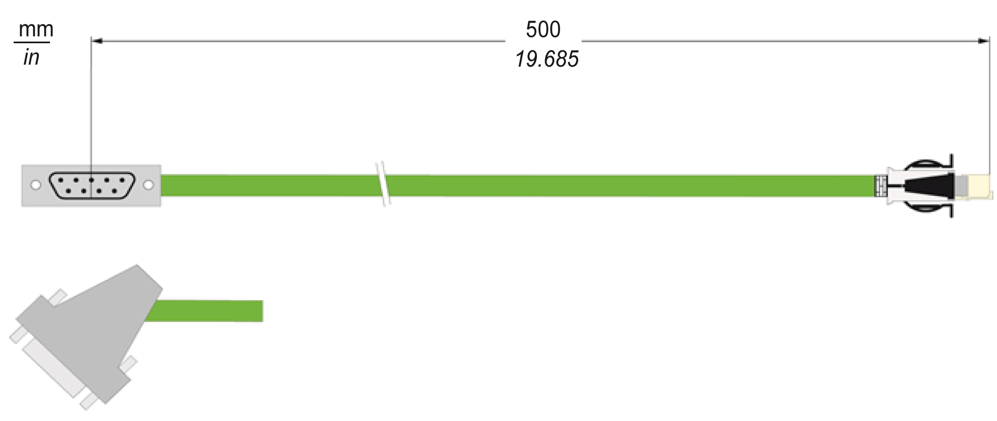
RJ45 Connector - 5V Encoder Adapter Input
The RJ45 connector is connected to the connection CN7/CN9 of the drive. Pin assignment of the RJ45 connector is identical to the pin assignment for the connection CN7/CN9 of the drive.
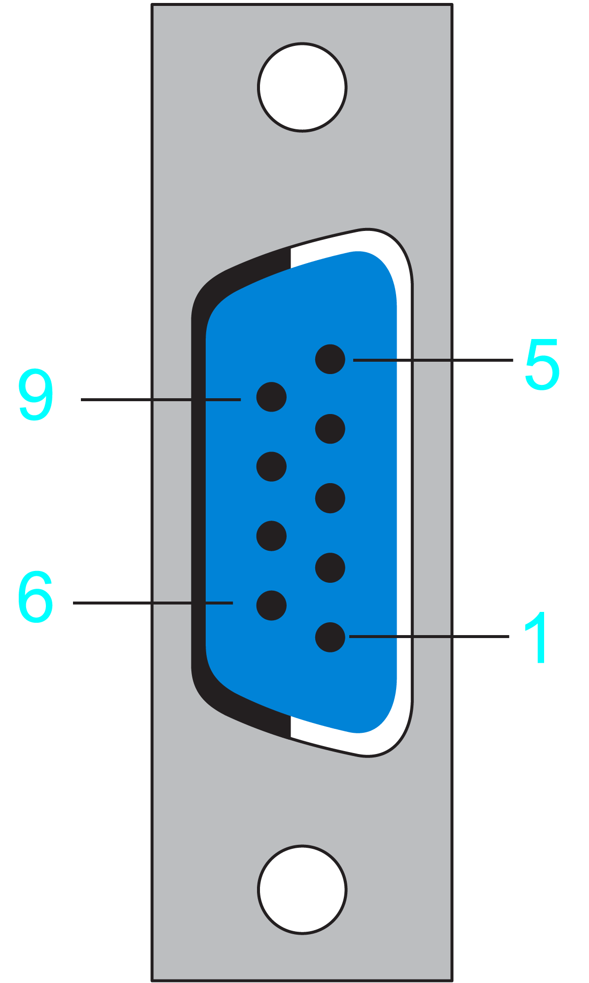
D-Sub 9-Pin Female Connector - 5V Encoder Adapter Output
The D-Sub 9-pin female connector is connected to the D-Sub 9-pin male connector of the encoder cable (user wired).

|
Pin |
Designation |
Description |
Range |
|---|---|---|---|
|
1 |
SIN |
Positive sine signal |
1 Vpp ±0.1 V |
|
2 |
Ref_Sin |
Negative sine signal |
Offset 2.5 ±0.3 V |
|
3 |
COS |
Positive cosine signal |
1 Vpp ±0.1 V |
|
4 |
Ref_Cos |
Negative cosine signal |
Offset 2.5 ±0.3 V |
|
5 |
RS485+ |
Positive RS-485 signal |
– |
|
6 |
P5V |
5 V encoder supply voltage |
5 V ±1% / Iout_max=250 mA |
|
7 |
P10V |
10 V encoder supply voltage |
10 V ±5% / Iout_max=125 mA |
|
8 |
RS485- |
Negative RS-485 signal |
– |
|
9 |
GND |
Encoder return |
0 V |
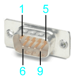
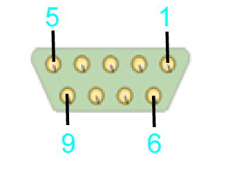
D-Sub 9-Pin Male Connector - Encoder Cable (Assembled by the Customer)
View mating side

View soldering side

|
Pin |
Designation |
Description |
Range |
|---|---|---|---|
|
1 |
SIN |
Positive sine signal |
1 Vpp ±0.1 V |
|
2 |
Ref_Sin |
Negative sine signal |
Offset 2.5 ±0.3 V |
|
3 |
COS |
Positive cosine signal |
1 Vpp ±0.1 V |
|
4 |
Ref_Cos |
Negative cosine signal |
Offset 2.5 ±0.3 V |
|
5 |
N.C. |
Reserved |
– |
|
6 |
P5V |
5 V encoder supply voltage |
5 V ±1% / Iout_max=250 mA |
|
7 |
P10V |
10 V encoder supply voltage |
10 V ±5% / Iout_max=125 mA |
|
8 |
N.C. |
Reserved |
– |
|
9 |
GND |
Encoder return |
0 V |
