Reading and Writing ASi Data Bits in EcoStruxure Machine Expert™ – Safety
This topic contains the following information:
After having added an ASi Gateway in EcoStruxure Machine Expert™ and parameterizing it in EcoStruxure Machine Expert™ – Safety, its data can be used in the safety-related application.
The communication between the SLC (and LMC) and the ASi Gateway via the openSafety over Sercos is accomplished by means of the 'x Bytes Safe Sercos Data' device object (with x = 8 for the BWU2984 and x = 12 for the ASi-5/ASi-3 Gateway) you have inserted under the gateway node. This topic describes how to use the data bits contained in this device object in the safety-related application.
Data bits read from/written to the ASi Gateway
The ASi Gateway appears as subslot of the SLC in the EcoStruxure Machine Expert™ – Safety Devices tree ('Devices' window), similar to a bus coupler device.
Example: ASi Gateway BWU2984 with device ID SL1.SM2
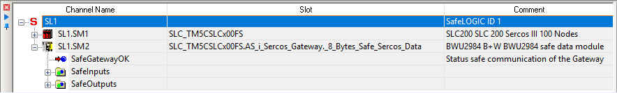
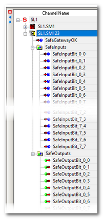
The data bits provided in the '8 Bytes Safe Sercos Data' device object of this particular ASi Gateway BWU2984 are grouped by input and output bits under the gateway node. 64 input bits as well as 64 output bits are provided per ASi Gateway. Additionally, the SafeGatewayOK signal is provided that indicates the communication status.
Example: ASi Gateway BWU2984
Note that the ASi-5/ASi-3 Gateway provides a '12 Bytes Safe Sercos Data' device object with 96 input bits and 96 output bits.
The meaning of the input and output data bits and which bits are used in your application depend on the user-defined and project-specific ASi data mapping made in your ASi application (in ASIMON360).
The entire bit set is transmitted to/from the ASi Gateway, independently of the ASi data mapping or the number/types of ASi I/Os that are physically connected to the ASi field bus. Input bits that are not used because they are not mapped to any ASi data remain SAFEFALSE permanently. Which data bits are used and have to be read or written in the safety-related SLC application (as they are mapped to a physically connected sensor or actuator) have to be determined in the ASIMON360 application.
By evaluating the relevant input bits coming from the ASi Gateway (delivering status information from ASi sensors and command devices) and writing the output bits transferred to the ASi Gateway (for example, to control ASi actuators), the safety-related SLC application can react on safety-related requests from the ASi field bus.
The input/output bits can be inserted like other process data items into the safety-related FBD/LD code by dragging them from the Devices tree (see following procedure). On insertion into the code, a safety-related global variable is created.
Additionally, each safety-related input/output bit is available as mirrored bit in EcoStruxure Machine Expert™.
Mirrored bits in EcoStruxure Machine Expert™
The safety-related input and output bits are mirrored in EcoStruxure Machine Expert™ in the 'sercos Module I/O Mapping' editor of the device object 'x Bytes Safe Sercos Data' relating to this ASi Gateway device (with x = 8 for the BWU2984 and x = 12 for the ASi-5/ASi-3 Gateway). After mapping an input/output bit to a Boolean variable in EcoStruxure Machine Expert™, the safety-related project is updated accordingly and the name of the mapped variable is entered into the 'LogicBuilder Variable' column in EcoStruxure Machine Expert™ – Safety.
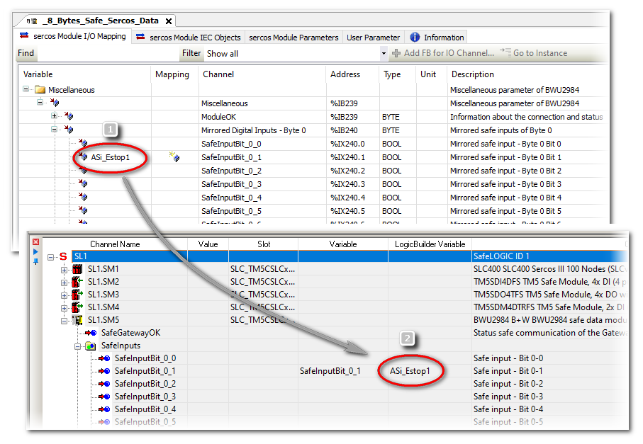
Example: ASi Gateway BWU2984
EcoStruxure Machine Expert™: in the 'sercos Module I/O Mapping' editor of the '8 Bytes Safe Sercos Data' device object, the variable 'ASi_Estop1' is mapped to the input bit 0-1 (number (1) in the figure below).
In EcoStruxure Machine Expert™ – Safety: the 'ASi_Estop1' variable is visible in the 'LogicBuilder Variable' column in the 'Devices' window (number (2) in the figure below). In this example, input bit 0-1 is already used in the safety-related application under the variable name 'SafeInputBit_0_1'. This variable name has automatically been created when dragging the bit into the safety-related application.
Assumptions for this documentation
For the descriptions given here we assume the following:
-
The type ASi Gateway BWU2984 is used which provides an '8 Bytes Safe Sercos Data' device object.
-
A direct 1:1 data mapping, that is to say, the address of an ASi device corresponds to the data bit number (input device 1 is mapped to input bit 0-1, etc.).
-
The input bits 0 and 32 are configured as diagnostic status bits.
-
The output bits 0 and 32 are configured as enable output bits.
Refer to the chapter "Configuration of the ASi functionality in ASIMON360" and to section "Description of the ASi input/output bits" for details.
Description of the ASi input/output bits (type ASi Gateway BWU2984)
The following applies to the '8 Bytes Safe Sercos Data' device object (that is to say, for the BWU2984 ASi-3 Gateway). For the ASi-5/ASi-3 Gateway with its '12 Bytes Safe Sercos Data' device object, other values for the device object size, bit numbers etc. apply accordingly.
SafeGatewayOK status bit
|
Description |
Safety-related status bit coming from the ASi Gateway indicating the status of the communication between the SLC and the ASi Gateway via openSafety over Sercos. The SafeGatewayOK signal can be evaluated together with the diagnostic signals that indicate the ASi circuit status (also delivered by the ASi Gateway). The present documentation is predicated on the best practice application in which these diagnostic bits are mapped to the input data bits 0 (for circuit 1) and 32 (for circuit 2). Refer to section "Circuit status monitoring: input bits 0 and 32..." below for details.
Representation in the Devices tree: |
|
Data type |
SAFEBOOL |
|
Access type |
Variable can be read by the safety-related SLC application. |
|
Possible values |
SAFEFALSE:
SAFETRUE:
NOTE:
Also observe the status display at the ASi Gateway for the error indication. |

Input bits 1 to 31 and 33 to 63
|
Description |
Safety-related input bit coming from the ASi Gateway.
Representation in the Devices tree:
NOTE:
The present documentation is predicated on the best practice application in which the input bits 0 and 32 are configured for monitoring the status of the ASi circuits 1 and 2 (see section below). As we use a direct 1:1 data mapping, the bit number directly corresponds to an ASi device address. Refer to your project documentation of the ASi application (made using ASIMON360) for details of your ASi data mapping. |
|
Data type |
SAFEBOOL |
|
Access type |
Variable can be read by the safety-related SLC application. |
|
Possible values |
SAFEFALSE and SAFETRUE. The meaning of the bit values SAFETRUE and SAFEFALSE depends on the ASi data mapping and your ASi application. As we use a direct 1:1 data mapping (ASi device address = bit number), the following applies: SAFEFALSE:
SAFETRUE:
NOTE:
A SAFETRUE value is only valid if the SafeGatewayOK signal and the diagnostic status signal for the corresponding ASi circuit are both SAFETRUE. The present documentation is predicated on the best practice application in which the diagnostic signal for circuit 1 is mapped to input data bit 0 and the diagnostic bit for circuit 2 is mapped to input bit 32. Refer to section "Circuit status monitoring: input bits 0 and 32..." below for details.
NOTE:
Also observe the status display at the ASi Gateway for the error indication. |
Output bits 1 to 31 and 33 to 63
|
Description |
Safety-related output bit written to the ASi Gateway.
Representation in the Devices tree:
NOTE:
The present documentation is predicated on the best practice application in which the output bits 0 and 32 are configured for enabling the ASi circuits 1 and 2 (see section below). As we use a direct 1:1 data mapping, the bit number may directly correspond to an ASi actuator ID. Refer to your project documentation of the ASi application (made using ASIMON360) for details of your ASi data mapping. |
|
Data type |
SAFEBOOL |
|
Access type |
Variable can be written by the safety-related SLC application. |
|
Possible values |
SAFEFALSE and SAFETRUE. The meaning of the bit values SAFETRUE and SAFEFALSE depends on the ASi data mapping and your ASi application. As we use a direct 1:1 data mapping (ASi device address = bit number), the following applies:
NOTE:
The present documentation is predicated on the best practice application in which the output bits 0 and 32 are configured for enabling the ASi circuits 1 and 2. This way, the value SAFETRUE written to an output bit can only become effective in the output process data image of the ASi Gateway (and therefore on the addressed ASi field bus circuit) if the related enable output signal (output bit 0 or 32) enables the respective ASi Gateway circuit with the value SAFETRUE. Output data bit 0 controls circuit 1, output bit 32 controls circuit 2 (see section below). |

Circuit status monitoring: input bits 0 and 32 correspond to TM5/TM7 SafeModuleOK signal
If configured in ASIMON360, the ASi Gateway provides diagnostic status signals for both ASi circuits (similar to the SafeModuleOK signal from TM5/TM7 modules). The present documentation is predicated on the best practice application in which you have implemented these diagnostic signals as follows:
-
The diagnostic status signals are mapped in ASIMON360 to the input bits 0 and 32 of the '8 Bytes Safe Sercos Data' device object. Input data bit 0 then represents the status of ASi circuit 1, and input bit 32 represents circuit 2.
-
The input bits 0 and 32 are evaluated in your safety-related SLC application in a way that the signals coming from the ASi devices are considered as invalid if the related circuit status signal is not SAFETRUE.
Additionally, the SafeGatewayOK signal is available to indicate the status of the communication between SLC and ASi Gateway via openSafety over Sercos. SafeGatewayOK = SAFEFALSE indicates that the safety-related communication via openSafety over Sercos is not established correctly.
|
Description |
Indicates the status of the respective ASi circuit and therefore, from safety-related application perspective, the ASi Gateway status itself. If mapped as described above, input data bit 0 represents circuit 1, and input bit 32 represents circuit 2. |
|
Data type |
SAFEBOOL |
|
Access type |
Variable can be read by the safety-related SLC application. |
|
Possible values |
SAFEFALSE: the respective ASi circuit is not available for the SLC. The data bits contained in the '8 Bytes Safe Sercos Data' device object are not valid. SAFETRUE: the respective ASi circuit is available for the SLC. The data bits contained in the '8 Bytes Safe Sercos Data' device object are valid. |
Circuit enabling: output bits 0 and 32 correspond to TM5/TM7 ReleaseOutput signal
The present documentation is predicated on the best practice application in which you have implemented enable output signals for the ASi circuits as follows:
-
Suitable Boolean output variables generated in the safety-related SLC application are provided as enable signals for each of the output ASi circuits.
-
These enable (or release) signals are mapped to the output bits 0 and 32 of the '8 Bytes Safe Sercos Data' device object.
-
These output bits 0 and 32 are processed in the ASIMON360 application using logical AND combinations in a way that a device may only activate its output if the enable signal is SAFETRUE.
This way, the output bits 0 and 32 of the '8 Bytes Safe Sercos Data' device object can be used for enabling the circuits 1 and 2 (similar to the ReleaseOutput signal known from TM5/TM7 modules). Setting an enable bit to SAFETRUE means that the related ASi devices may activate their outputs.
|
Description |
If configured as described above, the output bits 0 and 32 are the release signals for the ASi circuits. If mapped as described above, output data bit 0 controls circuit 1, and output bit 32 controls circuit 2. Ensure that setting an output bit to TRUE does not result in any hazards. Refer to the hazard message below this table. |
|
Data type |
SAFEBOOL |
|
Access type |
Variable can be written by the safety-related SLC application. |
|
Possible values |
|
| WARNING | |
|---|---|
How to insert data bits into the safety-related code
Use the input/output bits provided under the gateway node as follows in the safety-related application in EcoStruxure Machine Expert™ – Safety.
-
Read the status information (input bits) coming from the ASi Gateway and evaluate them in the safety-related application. It depends on the ASi I/O mapping defined in the ASi application (ASIMON360 project) to which ASi sensor(s)/command device(s) a bit corresponds. Also evaluate the SafeGatewayOK signal in the safety-related application.
-
Write the control signals (output bit) transferred to the ASi Gateway depending on the evaluated status information. It depends on the ASi I/O mapping defined in the ASi application (ASIMON360 project) to which ASi actuator(s) a bit corresponds. The present documentation is predicated on the best practice of a 1:1 data mapping application.
| WARNING | |
|---|---|
The bits have to be inserted into FBD/LD code worksheets as follows:
|
Download of parameterization/application data to the ASi Gateway
After having parameterized the ASi Gateway and used the ASi data bits in the safety-related code as described above, the related data are part of the safety-related EcoStruxure Machine Expert™ – Safety project which is in turn integrated in the non-safety-related EcoStruxure Machine Expert™ project. These data are included into the project download and then transferred from the LMC to the ASi Gateway. No separate download to the ASi Gateway is required.
The ASi application configuration developed using ASIMON360 has to be commissioned separately as described in the ASIMON360 user documentation.
Observe the following instructions before commissioning the system including the coupled ASi field bus:
| WARNING | |
|---|---|