Embedded I/Os Configuration
Overview
The embedded I/O function allows configuration of the controller inputs and outputs.
The TM262• controllers provide:
-
4 fast inputs
-
4 fast outputs
Accessing the I/O Configuration Window
Follow these steps to access the I/O configuration window:
|
Step |
Description |
|---|---|
|
1 |
Double-click (digital inputs) or (digital outputs) in the . Refer to Devices tree. |
|
2 |
Select the tab. |
Configuration of Digital Inputs
This figure shows the tab for digital inputs:
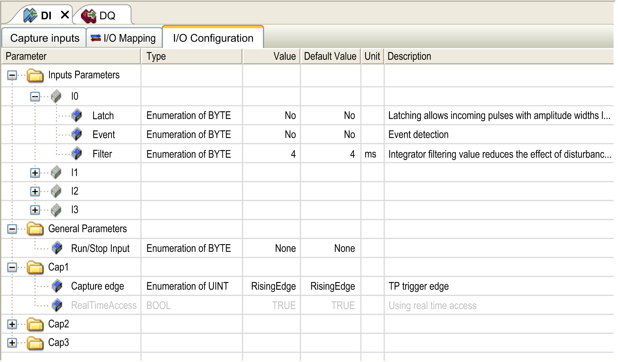
Digital Input Configuration Parameters
For each digital input, you can configure the following parameters:
|
Parameter |
Value |
Description |
Constraint |
|---|---|---|---|
|
|
0.000 ms 0.001 ms 0.002 ms 0.005 ms 0.01 ms 0.05 ms 0.08 ms 0.5 ms 1 ms 4 ms* 12 ms |
Reduces the effect of noise on a controller input. |
Configure to 0.000 if you do not want to filter the signal. |
|
|
No* Yes |
Allows incoming pulses with amplitude widths shorter than the controller scan time to be captured and recorded. |
Available if disabled. |
|
|
No* Rising edge Falling edge Both edges |
Event detection |
Available if disabled. When is selected, and the input state is TRUE before the controller is powered on, the first falling edge is ignored. |
|
|
None* I0...I3 |
The Run/Stop input can be used to run or stop the controller application. |
Select one of the inputs to use as the Run/Stop Input. |
|
* Parameter default value |
|||
Run/Stop Input
This table presents the different states:
|
Input states |
Result |
|---|---|
|
State 0 |
Stops the controller and ignores external Run commands. FSP LED is red ON. |
|
A rising edge |
From the STOPPED state, initiate a start-up of an application in RUNNING state, if no conflict with Run/Stop switch position. |
|
State 1 |
The application can be controlled by:
Run/Stop command is available through the Web server command. |
Inputs assigned to configured expert functions cannot be configured as Run/Stop inputs.
For further details about controller states and states transitions, refer to Controller State Diagram.
| WARNING | |
|---|---|
Capture Input
tab allows you to select captures, exclusively for motion applications, and manage them in the tab.
For each capture, you can configure the following parameters:
|
Parameter |
Type |
Value |
Description |
Constraint |
|---|---|---|---|---|
|
|
|
|
Configure the edge on which the encoder position is captured. |
Enable the capture positions in tab. Do not use with the function blocks from the Library. |
|
|
|
|
Using real time access. |
Enable the capture positions in tab. Do not use with the function blocks from the Library. |
For more information on motion applications and function blocks, such as and , refer to M262 Synchronized Motion Control Library Guide.
Configuration of Digital Outputs
This figure shows the tab for digital outputs:
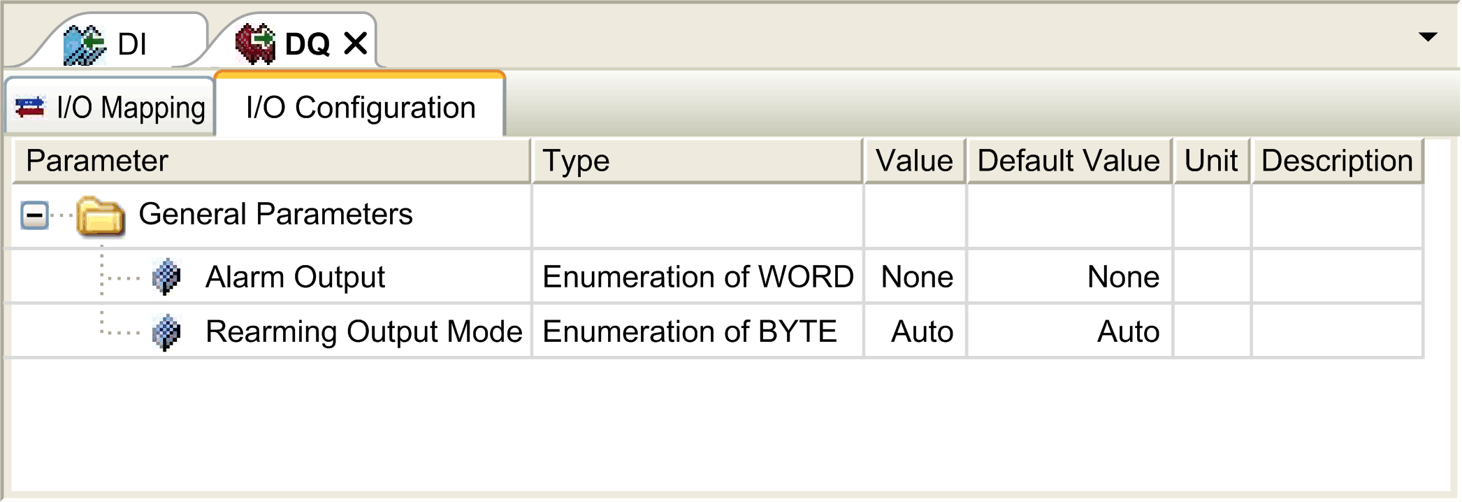
Digital Output Configuration Parameters
This table presents the function of the different parameters:
|
Parameter |
Function |
|---|---|
|
|
|
|
Alarm Output |
Select an output to be used as alarm output. |
|
Rearming Output Mode |
Select the rearming output mode. |
Alarm Output
This output is set to logical 1 when the controller is in the RUNNING state and the application program is not stopped at a breakpoint.
The alarm output is set to 0 when a task is stopped at a breakpoint to signal that the controller has stopped executing the application and when the controller is stopped.
Rearming Output Mode
Fast outputs of the Modicon M262 Logic/Motion Controller use push/pull technology. In case of detected error (short-circuit or over temperature), the output is put in the default value and the condition is signaled by status bit and PLC_R_IO_STATUS. This is also signaled by %IX1.0.
Two behaviors are possible:
-
Automatic rearming: as soon as the detected error is corrected, the output is set again according to the current value assigned to it and the diagnostic value is reset.
-
Manual rearming: when an error is detected, the status is memorized and the output is forced to the default value until user manually clears the status (see I/O mapping channel).
In the case of a short-circuit or current overload, the common group of outputs automatically enters into thermal protection mode (all outputs in the group are set to 0), and are then periodically rearmed (each second) to test the connection state. However, you must be aware of the effect of this rearming on the machine or process being controlled.
| WARNING | |
|---|---|