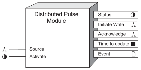
Distributed Pulse Module
The Distributed Pulse Module allows you to automatically transfer pulses from a Virtual Processor to another ION node such as an IED or different Virtual Processor. This module is only available in the VIP.
Module icon
![]()
Overview
When the Distributed Pulse Module is enabled, a pulse occurring at the Source input is written to the ION node you have specified.
NOTE: It is highly recommended that you use a Data Monitor Module in conjunction with this module. See the Data Monitor Module description for an example.
When used in conjunction with the other Arithmetic and External Control modules, the Distributed Pulse Module becomes a powerful tool for automated plant-wide demand or power factor control, including load shedding and start-up of auxiliary power.

Inputs
 Source
All Distributed Pulse Modules have one Source input. When a pulse is detected at this input, it is written to the node address you specify in the Destination setup register.
 Activate
This input allows you to manually activate or deactivate the Distributed Pulse Module.
By linking the Status output of a Data Monitor Module to this input, the Distributed Pulse Module will be automatically disabled if the data at the Source input becomes out-of-date, thus preventing a control action based on old data. Linking this input is mandatory.
Setup registers
 Destination
This register allows you to specify a node and register to which the value at the Source input will be written. This register displays the available nodes, module managers, modules and output registers from which you can select. Typically, you will select the output register of an External Pulse Module.
 EvPriority (event priority)
This register allows you to assign priority levels to specific event conditions.
Output registers
 Status
This Boolean register indicates the status of the last write. An on state indicates that the last write succeeded. An off state indicates time-outs, communication errors, or other failures. A not available value indicates that the module’s Activate input was not linked.
 Initiate Write
This output will generate a pulse when the Distributed Pulse Module sends its Source input value to the address specified in the Destination setup register.
 Acknowledge
This output will generate a pulse after a successful write. This occurs when the Distributed Pulse Module receives an acknowledgment from the device specified in the Destination setup register.
 Time to Update
This numeric output register reports the time (in seconds) between an Initiate Write pulse and the resulting Acknowledge pulse. A not available value indicates that the module’s Activate input was not linked.
 Event
Event
This output register is used to record the module’s successful and/or unsuccessful attempts in writing to the Destination register. For each event type written into the Event register, the following priority information is included:
| Event priority group | Priority | Description |
|---|---|---|
| Setup Change | 10 | Input links, setup registers or labels have changed. |
| Source Value Change | * | Write initiated (send the message). |
| Source Value Change | * | Write overwritten (Source changed before the last write got through. Resend with a new value and discard previous attempt). |
| Write Succeeded | * | Write complete and the destination has been updated. |
|
Write Failed Write Timeout Got Comm Error Got Invalid Node |
* | Write did not complete and destination was not changed. |
| * The priority of these events is determined by the value in the EvPriority setup register. | ||
The Event output register also contains the time stamp, priority, cause, effect, and any values or conditions associated with the cause and effect of the event.
Detailed module operation
When this module is enabled and the Source input detects a pulse, the Distributed Pulse Module automatically writes this information to the address specified in the Destination setup register.