Data Monitor Module
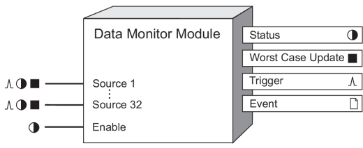
The Data Monitor Module provides a means of alerting you about communication problems that may occur between the Virtual Processor and any other node referenced by the Data Monitor’s Source inputs.
Module icon
![]()
Overview
This module is designed to be used in conjunction with the distributed control modules:
NOTE: For time-critical applications such as distributed control, it is highly recommended that you have one Virtual Processor dedicated for these tasks. Use a different Virtual Processor to perform other noncritical functions.
The Data Monitor Module ensures that the above modules’ control decisions will be made based only on fresh, valid data. Any communication problem occurring between the Data Monitor Module and the module it is monitoring will be indicated at the Data Monitor’s output registers.

NOTE: The registers and settings available in this module depend on the device or node you are configuring, as well as its firmware and template versions. Not all registers or settings are available on all devices or the Virtual Processor, and labels may vary.
Inputs


 Source 1...32
Each of the Source inputs can be linked to a Boolean, numeric or pulse output register of a module on another node. The Data Monitor checks for any communication problem occurring between itself and the modules connected to its Source inputs. Typically the Source inputs of the Data Monitor module will contain the data from remote nodes that are used by the Virtual Processor to make control decisions.
NOTE: You cannot link the Data Monitor’s Source inputs to modules contained in the same node as the Data Monitor Module .
 Enable
This input allows you to manually enable or disable the Data Monitor module. Linking this input is optional; if you leave it unlinked, the module will still operate and the Enable input will default to on.
Setup registers
 Worst Case Limit
This register defines the threshold for what is considered to be an acceptable time between updates (in seconds). The value you enter here is used by the module to determine what constitutes a communication problem or timing violation.
 EvPriority (event priority)
This register allows you to assign a priority level for the following event produced by the Data Monitor Module:
- Status output register changed from on to off.
Output registers
 Status
This Boolean register will be on under normal working conditions. If the update rate of any of the Source inputs falls below the threshold defined in the Worst Case Limit setup register, this register will switch to off, indicating a communication problem or timing violation. This output will be not available if no Source inputs have been linked or if the Enable input is linked, but turned off.
 Trigger
Every time the Status output register changes from on to off, the Trigger output register generates a pulse. No pulse is generated for off to on transitions.
 Worst Case Update
Every time the module operates, it checks the time to read from each of the linked Source inputs. The Worst Case Update register holds the value (in seconds) of the maximum time the module took to read from all its Source inputs. This value is equivalent to the maximum time the module has taken to read from all its linked Source inputs.
To capture the maximum value over a period of time, link the Source input of a Maximum Module to the Worst Case Update register. You can then view the maximum value using Vista.
 Event
Event
Any event produced by the Data Monitor Module is recorded in the Event register.
Possible events and their associated priority numbers are listed in the following table:
| Event priority group | Priority | Description |
|---|---|---|
| Setup Change | 10 | Input links, setup registers or labels have changed. |
| Status Register Change | * | Boolean output has changed from on to off. One source is not responding within the timeframe set by Worst Case Limit setup register. |
| * The priority of these events is determined by the value in the EvPriority setup register. | ||
The Event output register stores the following information for each ION event: time stamp, event priority, event's cause, event's effect, and conditions associated with the event's cause and effect.
Detailed module operation
The Data Monitor Module monitors the time between updates for each of the Source inputs. If the update period of any of the Source inputs exceeds the value specified in the Worst Case Limit setup register, the Status output register will turn off, and a pulse will be sent to the Trigger output register, indicating a communication problem. The Event register identifies which of the Source inputs is responsible for this problem. The slowest update rate (for all inputs) is held in the Worst Case Update output register. The Data Monitor Module provides a means of verifying that all sources connected to it are responding in a timely manner. Consider the following example.
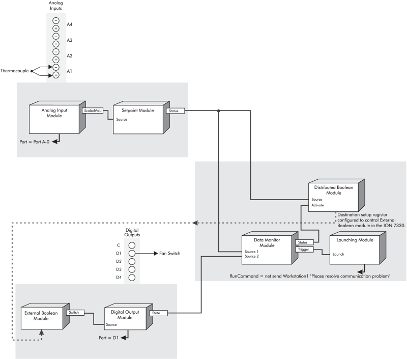
The following illustration shows how a control framework can be used to detect temperature extremes, switch on other equipment, and alert personnel of communication problems.
Consider this situation where a thermometer is monitoring the internal temperature of a piece of equipment. The thermometer’s output is connected to an analog input port on the ION7550. An Analog Input module is used to configure this port. The output of the Analog Input module is connected to a Setpoint module; this Setpoint module is used to initiate the control action.
The Status output of the Setpoint module is then used to link
the Source inputs of the Distributed Boolean
module and Data Monitor Module in the Virtual Processor. The Distributed
Boolean module is used for controlling the data appearing at the Switch register of the External Boolean module in the
Now assume that another device, the

How it works
When the specified temperature limit is reached (according to how you configure the Setpoint Module’s setup registers), the Status output register on the Setpoint module turns on, which then turns the Distributed Boolean Module on.
The Data
Monitor Module is used to detect communication problems between the
Virtual Processor and other nodes (in this case, the
When the Data Monitor’s status switches from on to off, it generates a pulse at its Trigger output register. This trigger is linked to a Launching module. The Launching module will then start another application (for example, network messaging or dialing a pager) to indicate the communication problem. In this example, a network message will be sent to the computer named “Workstation1.” The operator at this station can then investigate the cause of the communication problem.