Modbus Master Map Module
The Modbus Master Map Module provides a common location to hold the setup information needed for decoding a Modbus response (i.e. label, Modbus register address, formatting, scaling, etc.). One Modbus Master Map Module holds information that can be used by several Modbus Master Device Modules.
Module icon
![]()
Overview
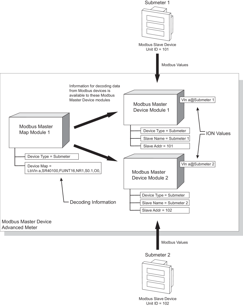
Modbus Master Device Modules are linked to (or associated with) a Modbus Master Map Module when you specify the same Device Type for both the Modbus Master Map and the Modbus Master Device modules.
For more information about Modbus and the ION architecture, see Modicon Modbus in the Modbus Import Module.

NOTE: The registers and settings available in this module depend on the device or node you are configuring, as well as its firmware and template versions. Not all registers or settings are available on all devices or the Virtual Processor, and labels may vary.
Inputs
The Modbus Master Map Module has no inputs.
Setup registers
The Modbus Master Map Module has the following setup registers:
 Device Type
This string register defines the slave device type. The string can have a maximum of 20 alphanumeric characters; dot and dash allowed.
NOTE: The Device Type setup register entry must match exactly the Device Type setup register entry of a Modbus Master Device module in order to operate. Both of these Device Type registers are case sensitive.
 Device Map
This string register contains the label, Modbus address, format and scaling information for each Modbus register. You can store mapping information for up to 32 Modbus registers within any 125 Modbus register block.
String example for an ION6200:
LbVln a,SR40100,FUINT16,NR1,S0.1,O0,
LbVln b,SR40101,FUINT16,NR1,S0.1,O0,
LbVln c,SR40102,FUINT16,NR1,S0.1,O0,
LbVln avg,SR40103,FUINT16,NR1,S0.1,O0,
LbVln ab,SR40104,FUINT16,NR1,S0.1,O0,
LbVln bc,SR40105,FUINT16,NR1,S0.1,O0,
LbVln ca,SR40106,FUINT16,NR1,S0.1,O0,
LbVll avg,SR40107,FUINT16,NR1,S0.1,O0
LbI a,SR40108,FUINT16,NR1,S0.1,O0,
LbI b,SR40109,FUINT16,NR1,S0.1,O0,
LbI c,SR40110,FUINT16,NR1,S0.1,O0,
LbI avg,SR40111,FUINT16,NR1,S0.1,O0,
LbI dmd,SR40112,FUINT16,NR1,S0.1,O0,
LbI pk dmd,SR40113,FUINT16,NR1,S0.1,O0,
LbI 4,SR40114,FUINT16,NR1,S0.1,O0,
LbFreq us,SR40115,FSINT16,NR1,S1,O0,
LbPF sign tot us,SR40116,FSINT16,NR1,S1,O0,
LbkW tot,SR40120,FSINT16,NR1,S1,O0,
LbkVAR tot,SR40121,FSINT16,NR1,S1,O0,
LbkVA tot,SR40122,FSINT16,NR1,S1,O0,
LbkWh del,SR40138,FU32-2143,NR2,S1,O0,
LbkWh rec,SR40140,FU32-2143,NR2,S1,O0,
LbkVARh del,SR40142,FU32-2143,NR2,S1,O0,
LbkVARh rec,SR40144,FU32-2143,NR2,S1,O0,
LbkVAh del+rec,SR40146,FU32-2143,NR2,S1,O0,
One line of an example string:

Each line contains commas and prefixes for each component (e.g. Label). You must always include these commas and prefixes in each line, in the exact places as above.
Label (prefix Lb)
This string field (minus the prefix) will be used within the output label on the associated Modbus Master Device Module. A maximum of 15 alphanumeric characters are allowed.
Starting Modbus Register (prefix SR)
This determines the starting Modbus register that will be read and decoded by the associated Modbus Master Device Module.
NOTE: All SR entries in the Device Map register must be from within the same function code.
See the following table for supported Modbus addresses and their functions:
| Function Name | Function Code | Register Address |
|---|---|---|
| READ_COIL_STATUS | 01 | 0XXXX(X) |
| READ_INPUT_STATUS | 02 | 1XXXX(X) |
| READ_HOLDING_REGISTERS | 03 | 4XXXX(X) |
| READ_INPUT_REGISTERS | 04 | 3XXXX(X) |
Format (prefix F)
This determines what format of data is followed when reading from this Modbus register(s). See the following table for supported Modbus formats:
| Format | Description | Type | Acceptable Range | # of Modbus Registers | Scaling/Offset? |
|---|---|---|---|---|---|
| UINT16 | 16-bit unsigned | Integer | 0 to 65,535 | 1 | Yes |
| SINT16 | 16-bit signed | Integer | -32,768 to 32,767 | 1 | Yes |
| UINT32 | 32-bit unsigned | Integer | 0 to 4,294,967,295 | 2 | Yes |
| SINT32 | 32-bit signed | Integer | -2,147,483,648 to 2,147,483,647 | 2 | Yes |
| S32-2143 | 32-bit signed LE | Integer | -2,147,483,648 to 2,147,483,647 | 2 | Yes |
| U32–2143 | 32–bit unsigned LE | Integer | 0 to 4,294,967,295 | 2 | Yes |
| U32-M10k-4321 | 32-bit unsigned M10k | Integer | 0 to 655,359,999 | 2 | Yes |
| U32-M10k-2143 | 32-bit unsigned M10K LE | Integer | 0 to 655,359,999 | 2 | Yes |
| S32-M10k-4321 | 32-bit signed M10K | Integer | -327,689,999 to 327,679,999 | 2 | Yes |
| S32-M10k-2143 | 32-bit signed M10K LE | Integer | -327,689,999 to 327,679,999 | 2 | Yes |
| PackedBool | Packed Boolean | Integer | 0 to FFFF (Boolean inputs) | 1 | No |
| IEEEFloat | IEEE Float | Floating Point | - 3.402823466x1038 to 3.402823466x1038 | 2 | No |
| SwappedFloat | IEEE Float Little Endian (LE) | Floating Point | - 3.402823466x1038 to 3.402823466x1038 | 2 | No |
M10k refers to the Modulo10000 formats. This format breaks a 32-bit value into two 16-bit registers, according to the following relationship:
- register_high (higher-order register) = value/10,000
- register_low (lower-order register) = value modulus 10,000
For positive values, the modulo result range is 0 to 9,999. For negative values, the modulo result range is -9,999 to 0.
Therefore, the 32-bit value can be retrieved by the following calculation:
value = register_high x 10,000 + register_low
Register Size (prefix NR)
This determines the size or number of registers that will be read and decoded. One register is 16-bit, two are 32-bit. Valid values are 1 and 2.
Scaling (prefix S)
This determines the scaling that will be applied to the Modbus values. This is used to compensate for scaling applied by the Modbus Slave device. The scaling value is divided into the Modbus value (see formula below). Valid values are +/- 1 x 10⁶ to +/- 1 x 10⁻⁶. A scaling value of one (S1) means no scaling will be applied (Modbus value will be divided by one)
Offset (prefix O)
This determines the offset that will be applied to the Modbus values. This is used to compensate for offset applied by the Modbus Slave device. The offset value is subtracted from the Modbus value (see formula below). Valid values are +/- 1 x 10⁶.
Offset and Scaling Applied
The following formula is applied to the value, when scaling and offset is used:

For example,
If the value read from the slave device is 2000, and the scaling is 0.1, the output value would be 20000.
NOTE: If the Device Map string register is configured incorrectly, Designer will produce a Device Map Setup Error when Sending & Saving. The message will advise where the error occurs in the string. Additionally, the Modbus Master Map module will go offline and any associated Modbus Master Device modules outputs will be N/A, until the error is corrected.
NOTE: The Modbus Master Map module maps Modbus registers to the Modbus Master Device output registers in ascending order. If you add or delete entries in an existing Device Map string, the Modbus Master Device output registers dynamically update to reflect the changes made to the Modbus Master Map Device Map.
For example:
- In the Modbus Master Map module, Amps A is mapped to Modbus Master Device module Value1, Watts 3-Ph total is mapped to Modbus Master Device module Value2.
- If you change the mapping to add Volts A-N, the Modbus Master Map module will require you to change the Modbus map register string so the Modbus registers are listed in order, i.e. Volts A-N first, then Amps A, then Watts 3-Ph total.
Before the change:
- Modbus Master Device module Value1 = Amps A
- Modbus Master Device module Value2 = Watts 3-Ph total
After the change:
- Modbus Master Device module Value1 = Volts A-N
- Modbus Master Device module Value2 = Amps A
- Modbus Master Device module Value3 = Watts 3-Ph total
Output registers
 Event
Event
All events are recorded in the Event register.
Possible events and their associated priority numbers are:
| Event priority group | Priority | Description |
|---|---|---|
| Reset | 5 | A module reset has occurred. |
| Setup Change | 10 | Setup registers or labels have changed. |
The Event output register stores the following information for each ION event: time stamp, event priority, event’s cause, event’s effect, and conditions associated with the event’s cause and effect.
Detailed module operation
The Modbus Master Map Module works in tandem with the Modbus Master Device module.
In the example below, two basic meters (Submeter1 and Submeter2) act as Modbus Slave devices and provide Modbus values to an advanced meter that acts as the Modbus Master device. Submeter1 is linked to Modbus Master Device module 1 (the meter’s Unit ID of 101 is entered in the Modbus Master Device module’s Slave Addr register) while Submeter2 is linked to Modbus Master Device module 2.
Modbus Master Device Module 1 collects Modbus data (Vln a) from Submeter1, while Modbus Master Device Module 2 collects Modbus data (Vln a) from Submeter2. These two Device modules then use the decoding information available from the Modbus Master Map Module 1 to translate the Modbus information into values other ION modules can use. Notice the Device Type register of all three modules is set to submeter. This “links” the Modbus Master Map Module to the two Modbus Master Device modules.
