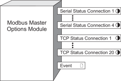
Modbus Master Options Module
The Modbus Master Options Module is a core module that maps any serial or Ethernet TCP connection from Modbus Import, Modbus Export and Modbus Master Device modules to a serial communications port or Ethernet TCP socket.
Module icon
![]()
Overview
For meters with Modbus gateway capability, it also maps the Modbus Gateway Connection register to that connection. You cannot delete this module or add another.
For more information on implementing the Modbus protocol (and Modbus Mastering), see the Modbus and ION Technology technical note, available from the website. For more information on using your meter as a Modbus gateway, see your meter’s User Guide.

NOTE: The registers and settings available in this module depend on the device or node you are configuring, as well as its firmware and template versions. Not all registers or settings are available on all devices or the Virtual Processor, and labels may vary.
Inputs
The Modbus Master Options Module has no inputs.
Setup registers
The Modbus Master Options Module has the following setup registers:
 Serial Connection 1-4
These enumerated registers map serial connections to serial communications ports. Choose none (default) or a communication port on your device that supports the Modbus Master Options module (for example, com1, com2, com3 or com4).
 TCP Connection 1-20
These string registers contain the IPv4 or IPv6 address and port number for the TCP connections, for example 123.45.67.89:502 or [fe80:0000:0000:0000:0260:78ff:fe04:2d60]:502. Up to 20 unique IP addresses can be mapped to Modbus master over Ethernet/TCP.
 Modbus Gateway
Connection
This enumerated register is configured if you want to use your meter as a Modbus gateway to communicate with downstream serial devices. If you want to use the meter as a Modbus gateway, it must be set to the Serial Connection register (above) that is mapped to the COM port used to communicate with the serial devices. That COM port must be configure to use Modbus Master protocol. The default setting is gateway disbaled, which disables the gateway functionality and allows the meter to respond to any Unit ID for Modbus TCP (port 502) or Modbus RTU (port 7701) requests. This is different from the gateway enabled — no connection setting, which sets the meter to respond only to Unit ID 255 and enables the gateway functionality even though no downstream devices are setup.
 Exception Code
This enumerated register determines the exception code that is returned if a downstream device fails to respond to a request. The exception code in current Modbus implementation is 0x0B. However, some legacy devices require the exception code to be 0x0A.
 ModGate Process
Broadcasts
This enumerated register determines how broadcast messages (with the Unit ID = 0) are handled by the meter acting as a Modbus gateway. When set to no (the default), the gateway meter sends the broadcast message to the downstream serial devices but ignores the message itself. When set to yes, the gateway meter processes the message itself and forwards it to the downstream devices.
 TCP Holdoff
This numeric bounded register provides a configuration method that allows you to change the 30 minute timeout for an unsuccessful Modbus TCP connection. Using this new method, the timeout can now be set to a value between 1 minute and 65535 minutes. After a third consecutive unsuccessful attempt to create a Modbus TCP connection as Modbus Master, the module does not attempt to make a connection again until the timeout value set in the register has been reached..
Output registers
 Serial Status Connection 1-4
These Boolean output registers indicate the status of the serial connections, using TRUE (YES) or FALSE (NO). TRUE indicates that the serial connection is configured in at least one Modbus Import module, Modbus Export module, or Modbus Master Device module, and that the communication port is set to the Modbus Master protocol.
 TCP Status Connection 1-20
These Boolean output registers indicate the status of the Ethernet TCP connections, using TRUE (YES) or FALSE (NO). TRUE indicates that the TCP connection is configured in at least one Modbus Import module, Modbus Export module, or Modbus Master Device module.
 Event
Event
ION Events
are recorded in this output register.
| Event priority group | Priority | Description |
|---|---|---|
| Reset | 5 | A module reset has occurred. |
| Setup Change | 10 | Setup registers or labels have changed. |
The Event output register stores the following information for each ION event: time stamp, event priority, event cause, event effect, and conditions associated with the event’s cause and effect.
Detailed module operation
This module provides settings that affect the following modules for that particular session:
- Modbus Import Module
- Modbus Export Module
- Modbus Master Device Module
- Modbus Master Map Module
Module Update Rate
The update rate of the Modbus Import, Modbus Export and Modbus Master Device modules depends upon many factors, such as:
- Master and Slave loading
- serial and TCP parameters such as Receive Timeout and Transmit Delay
- serial and TCP baud rate and loading in the serial line or Ethernet
- number of requests to be performed
For more information about Modbus and the ION architecture, see Modicon Modbus in the Modbus Import Module.