Optional Interface Installation
Before installing or removing an interface, shut down Windows operating system in an orderly fashion and remove the power from the device.
|
|
|
HAZARD OF ELECTRIC SHOCK, EXPLOSION OR ARC FLASH |
|
oRemove all power from the device before removing any covers or elements of the system, and prior to installing or removing any accessories, hardware, or cables. oUnplug the power cable from both the Magelis Industrial PC and the power supply. oAlways use a properly rated voltage sensing device to confirm that power is off. oReplace and secure all covers or elements of the system before applying power to the unit. oUse only the specified voltage when operating the Magelis Industrial PC. The AC unit is designed to use 100...240 Vac input. The DC unit is designed to use 24 Vdc input. Always check whether your device is AC or DC powered before applying power. |
|
Failure to follow these instructions will result in death or serious injury. |
NOTE:
oThe operating temperature is 0...55 °C (131 °F) except with 2 x optional interfaces + display limited to 45 °C (113 °F).
oThe operating temperature for horizontal mounting for Box iPC Optimized (HMIBMO is limited to 45 °C (113 °F).
oThe operating temperature for Box iPC Optimized (HMIBMI) is limited to 45 °C (113 °F).
Optional Interface Compatible Table
|
Part number |
Description |
HMIBMP/HMIBMU |
HMIBMI/HMIBMO Expandable |
|---|---|---|---|
|
HMIYMINUSB1 |
Interface USB 3.0, 2 x USB |
Yes(1) |
Yes |
|
HMIYMINAUD1 |
Interface audio, 1 x LI/LO/MIC |
Yes(2) |
N/A |
|
HMIYMINSL24851 |
Interface 2 x RS-422/485 isolation |
Yes |
Yes |
|
HMIYMINSL44851 |
Interface 4 x RS-422/485 |
Yes |
Yes |
|
HMIYMINSL22321 |
Interface 2 x RS-232 isolation |
Yes |
Yes |
|
HMIYMINSL42321 |
Interface 4 x RS-232 |
Yes |
Yes |
|
HMIYMINAUD21 |
Interface audio 1 x LI/LO/MIC |
Yes(2) |
Yes |
|
HMIYMINATPM201 |
Interface TPM 2.0 |
Yes(9) |
Yes |
|
HMIYMINIO1 |
Interface 16 DI/8 DO, 1 x DB37, 2 m cable |
Yes |
Yes |
|
HMIYMIN8AI1 |
Interface 8 analog input |
Yes |
Yes |
|
HMIYMINWIFI1 |
Interface WiFi, AC3160, 2 x antenna |
Yes |
Yes |
|
HMIYMINGPRS1 |
Interface 3G, 1 x antenna |
Yes |
Yes |
|
HMIYMIN4GUS1 |
Interface 4G US, 1 x antenna |
Yes |
Yes |
|
HMIYMIN4GEU1 |
Interface 4G EU/ASIA, 1 x antenna |
Yes |
Yes |
|
HMIYADDPDVI11 |
Interface DP to DVI adaptor, active mode |
Yes |
Yes |
|
HMIYMINDVII1 |
Interface 1 x DVI-I |
Yes(4/5) |
Yes |
|
HMIYMINVGADVID1 |
Interface, 1 x DVI-D, 2 x VGA, two brackets |
Yes(4/5) |
Yes(3) |
|
HMIYMINDP1 |
Interface transmitter |
Yes(5/6/7) |
Yes(7) |
|
HMIYMINPRO1 |
Interface Profibus w/NVRAM |
Yes |
Yes |
|
HMIYMINCAN1 |
Interface fieldbus, 2 x CANopen |
Yes |
Yes |
|
(1) Only support one HMIYMINUSB1 in HMIBMP/HMIBMU. (2) Only support one HMIYMINAUD1 in HMIBMP/HMIBMU. HMIBMP/HMIBMU has pin header, so for Line in, Line out and Mic in, preferably use HMIYMINAUD1. (3) HMIBMO Expandable only support one Interface bracket; either with 2 x VGA or DVI-D bracket. (4) HMIYMINDVII1 and HMIYMINVGADVID1 cannot use together in HMIBMP/HMIBMU. (5) HMIYMINDP1 cannot use with HMIYMINDVII1 or HMIYMINVGADVID1. (6) HMIYMINDP1 and HMIYMINUSB1 cannot use together in HMIBMP/HMIBMU. (7) Remove the existing driver when you want to install HMIYMINDP1 or HMIYMINDVII1 or HMIYMINVGADVID1. (8) Cannot monitor UPS status because Display Adapter does not have COM port. (9) Need to downgrade to TPM 1.2 in HMIBMP/HMIBMU. |
|||
The figure shows the interface types (top view):
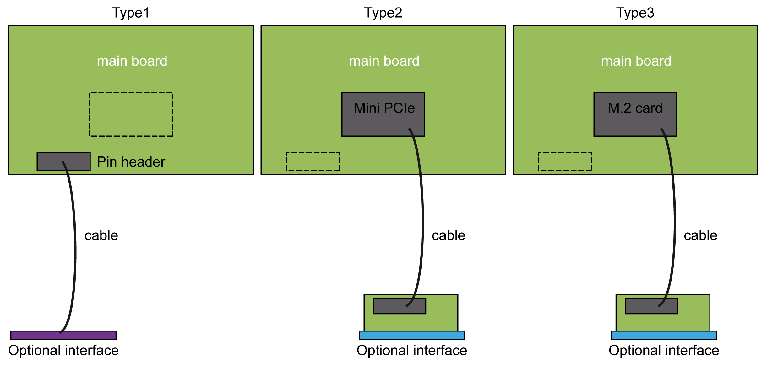
Type1 Pin header
Type 2 mini PCIe card
Type 3 M.2 card
The figure shows the possible interfaces:
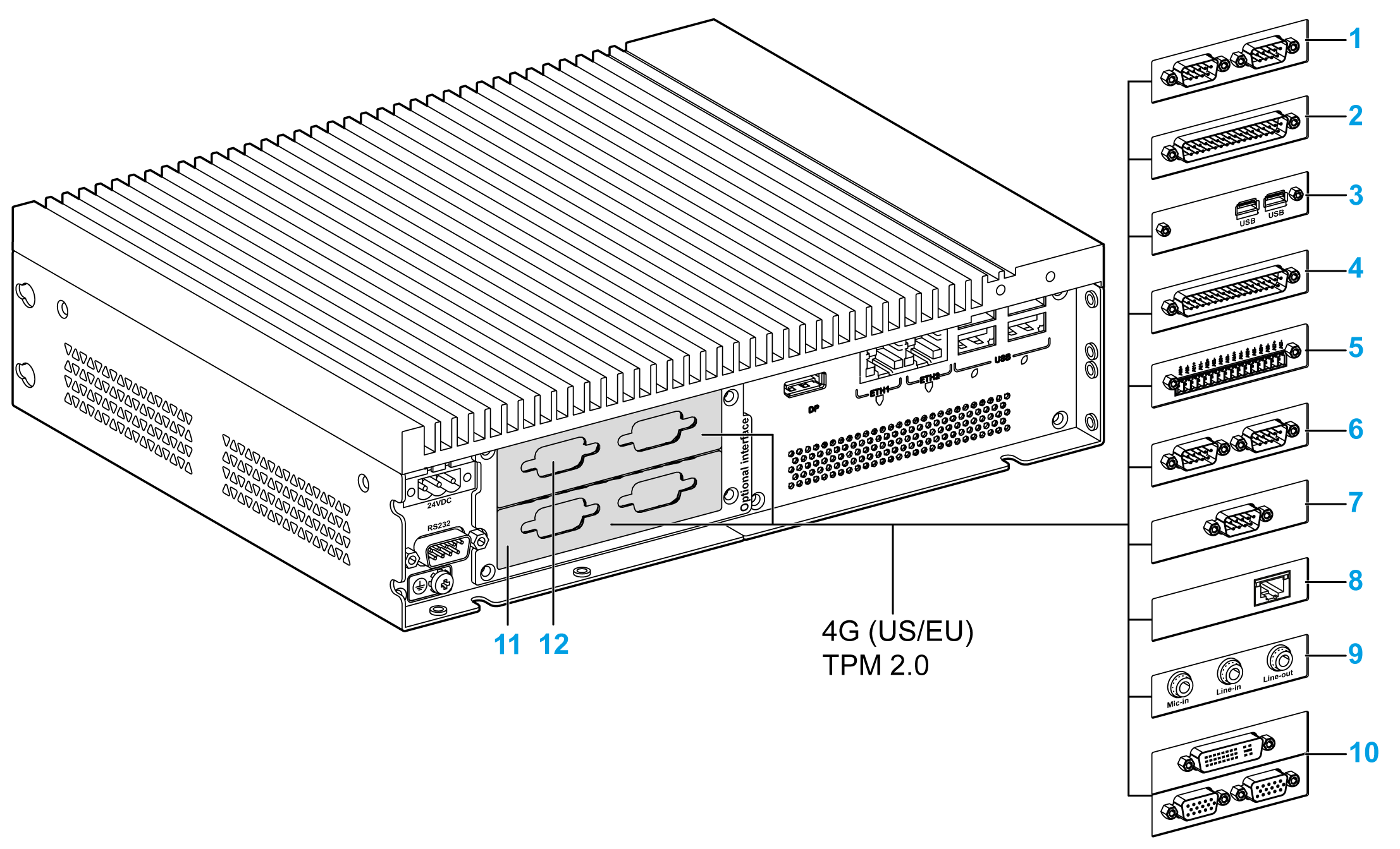
1 2 x RS-232, RS-422/485 interface
2 4 x RS-232, RS-422/485 interface
3 USB interface
4 DIO interface
5 Analog input interface
6 CANopen interface
7 Profibus DP interface
8 mini PCIe to Display Adapter Interface
9 Audio interface
10 VGA and DVI interface for the Box iPC Universal/Performance
11 Optional interface 1
12 Optional interface 2 for the Box iPC Universal/Performance
The table shows the type and part number of the optional interface:
|
Designation |
Part number |
Interface |
Type: |
||
|---|---|---|---|---|---|
|
mini PCIe card |
Interface plate |
Pin header from system |
|||
|
HMIYMINNVRAM1 |
Card NVRAM |
1 |
– |
– |
|
|
HMIYMINSL24851 |
2 x RS-422/485 isolated |
1 |
1 |
– |
|
|
HMIYMINSL44851 |
4 x RS-422/485 |
||||
|
HMIYMINSL22321 |
2 x RS-232 isolated |
||||
|
HMIYMINSL42321 |
4 x RS-232 |
||||
|
HMIYMINIO1 |
16 x DI / 8 x DO |
1 |
1 |
– |
|
|
HMIYMIN8AI1 |
8 x analog input |
1 |
1 |
– |
|
|
HMIYMINWIFI1 |
1 x Wireless LAN and 2 x antennas |
1 |
1 |
– |
|
|
HMIYMINCAN1 |
2 x CanOpen/CanBus |
1 |
1 |
– |
|
|
HMIYMINPRO1 |
1 x Profibus DP master NVRAM |
1 |
1 |
– |
|
|
USB interface |
HMIYMINUSB1 |
2 x USB 3.0 |
1 |
1 |
– |
|
Audio interface for Box iPC Universal/Performance |
HMIYMINAUD1 |
1 x Audio |
– |
1 |
1 |
|
Audio mini PCIe interface for Box iPC Optimized |
HMIYMINAUD21 |
1 x Audio |
1 |
1 |
– |
|
HMIYMINDP1 |
1 x Transmitter |
1 |
1 |
– |
|
|
HMIYMINDVII1 |
1 x DVI-I |
1 |
1 |
– |
|
|
VGA and DVI-D interface for Box iPC Universal/Performance |
HMIYMINVGADVID1 |
2 x VGA and 1 DVI-D |
1 |
2 |
– |
|
HMIYMINGPRS1 |
1 x GPRS/GSM |
1 |
– |
– |
|
|
HMIYMIN4GUS1 |
4G cellular for EU/Asia, antenna |
1 |
– |
– |
|
|
HMIYMIN4GEU1 |
4G cellular for US, antenna |
1 |
– |
– |
|
|
HMIYMINATPM201 |
– |
– |
– |
1 |
|
Before installing or removing a mini PCIe card, shut down Windows operating system in an orderly fashion and remove the power from the device.
The Box iPC HMIBMP, HMIPCCP2B, HMIBMU, HMIPCCU2B, HMIPCCU27, HMIPCCU2J, HMIPCCP27, HMIPCCP2J, and the Display Adapter HMIDADP11 are classified hazardous locations Class I Division 2 (see chapter "Certifications and Standards"). Observe the following:
|
|
|
EXPLOSION HAZARD |
|
oAlways confirm the ANSI/ISA 12.12.01 and CSA C22.2 N°213 hazardous location rating of your device before installing or using it in a hazardous location. oTo power on or power off a Magelis Industrial PC installed in a Class I, Division 2 hazardous location, you must either: oUse a switch located outside the hazardous environment, or oUse a switch certified for Class I, Division 1 operation inside the hazardous area. oSubstitution of any components may impair suitability for Class I, Division 2. oDo not connect or disconnect equipment unless power has been switched off or the area is known to be non-hazardous. This applies to all connections including power, ground, serial, parallel, network, and rear USB connections. oNever use unshielded / ungrounded cables in hazardous locations. oWhen enclosed, keep enclosure doors and openings closed at all times to avoid the accumulation of foreign matter inside the workstation. oDo not open lid nor use the USB connectors in hazardous locations. oDo not expose to direct sunlight or UV light source. |
|
Failure to follow these instructions can result in death, serious injury, or equipment damage. |
The Box iPC HMIBMI, HMIPCCP•2L, HMIPCCP•2N and the displays HMIDM9521, HMIDMA521 are not classified hazardous locations.
|
|
|
POTENTIAL FOR EXPLOSION IN HAZARDOUS LOCATION |
|
Do not use these products in hazardous locations. |
|
Failure to follow these instructions will result in death or serious injury. |
|
NOTICE |
|
ELECTROSTATIC DISCHARGE |
|
Take the necessary protective measures against electrostatic discharge before attempting to remove the Magelis Industrial PC cover. |
|
Failure to follow these instructions can result in equipment damage. |
|
|
|
OVERTORQUE AND LOOSE HARDWARE |
|
oDo not exert more than 0.5 Nm (4.5 lb-in) of torque when tightening the installation fastener, enclosure, accessory, or terminal block screws. Tightening the screws with excessive force can damage the installation fastener. oWhen fastening or removing screws, ensure that they do not fall inside the Magelis Industrial PC chassis. |
|
Failure to follow these instructions can result in injury or equipment damage. |
NOTE: Remove the power before attempting this procedure.
|
Step |
Action |
|---|---|
|
1 |
Disconnect the power cord from the Box iPC. |
|
2 |
Touch the housing or ground connection (not the power supply) to discharge any electrostatic charge from your body. |
|
3 |
Unscrew the nine screws from the cover and remove it: 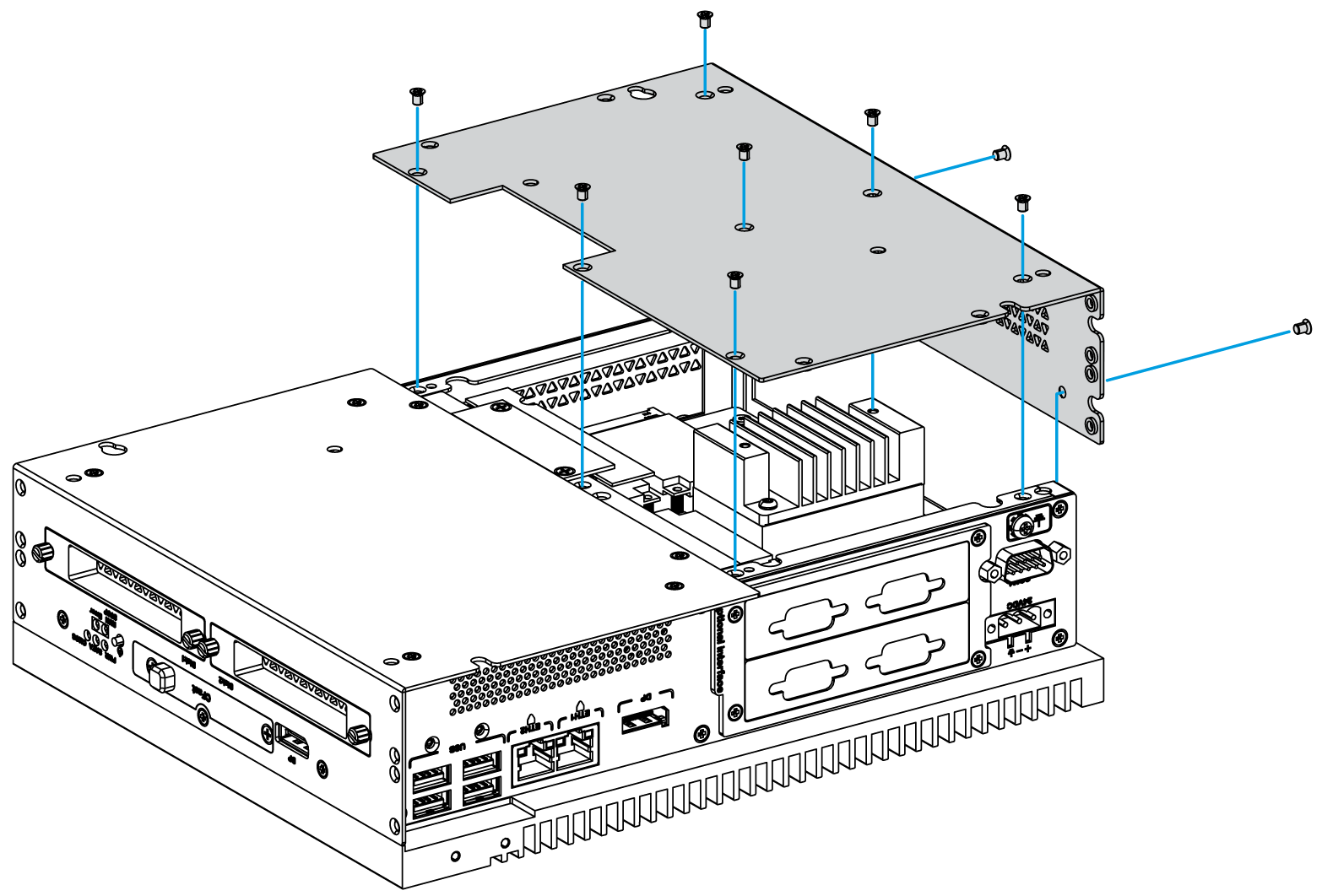
|
|
4 |
Insert the interface in the slot of the Box iPC Universal/Performance and fasten it to the Box iPC with four screws: 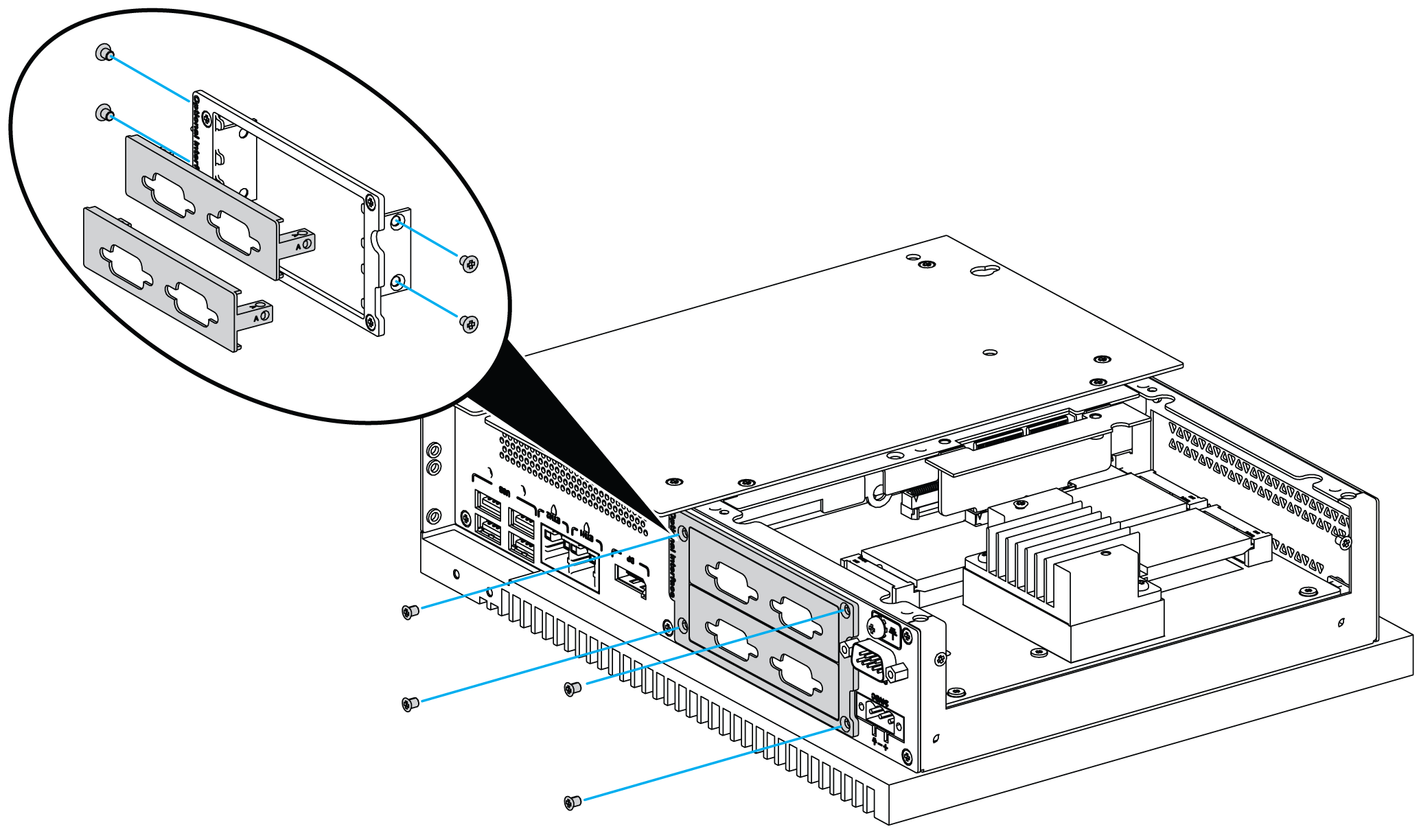
NOTE: The recommended torque to tighten these screws is 0.5 Nm (4.5 lb-in). |
|
5 |
Insert the mini PCIe card into the expansion card connector of the Box iPC Universal and fasten it with two screws: 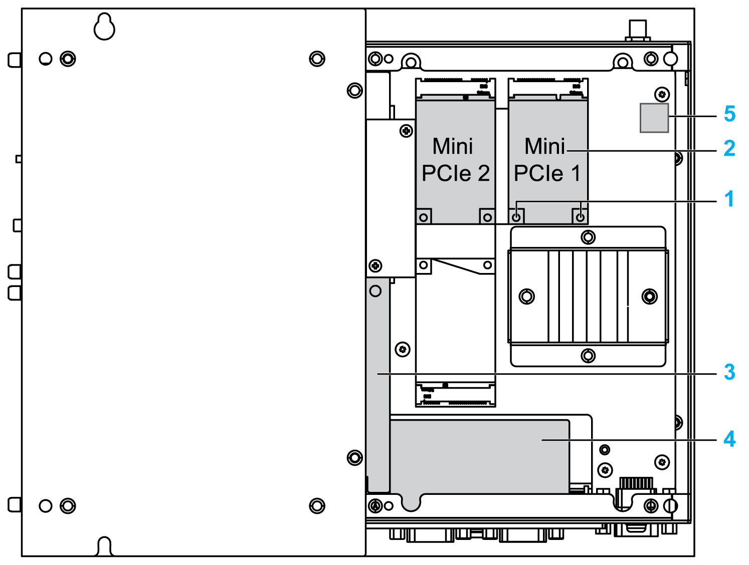
1 Screws 2 mini PCIe card 3 Pin header 4 Optional interface 5 TPM module The pin headers are for both USB interface and Audio interface. NOTE: oWhen using a mini PCIe card with an external cable attached, install a clamp or other device to secure the cable. oThe requirement of Phillips screw driver is type size 2. The recommended torque to tighten these screws is 0.5 Nm (4.5 lb-in). |
|
6 |
Replace the cover and fasten it with nine screws: 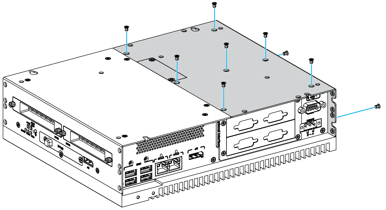
NOTE: The recommended torque to tighten these screws is 0.5 Nm (4.5 lb-in). |
|
Step |
Action |
|---|---|
|
1 |
Disconnect the power cord from the Box iPC. |
|
2 |
Touch the housing or ground connection (not the power supply) to discharge any electrostatic charge from your body. |
|
3 |
Unscrew the eight screws from the covers and remove them: 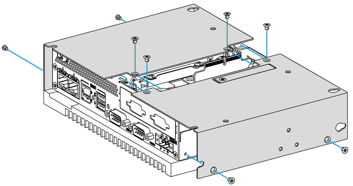
|
|
4 |
Insert the interface in the slot of the Box iPC Optimized and fasten it to the Box iPC with two screws: 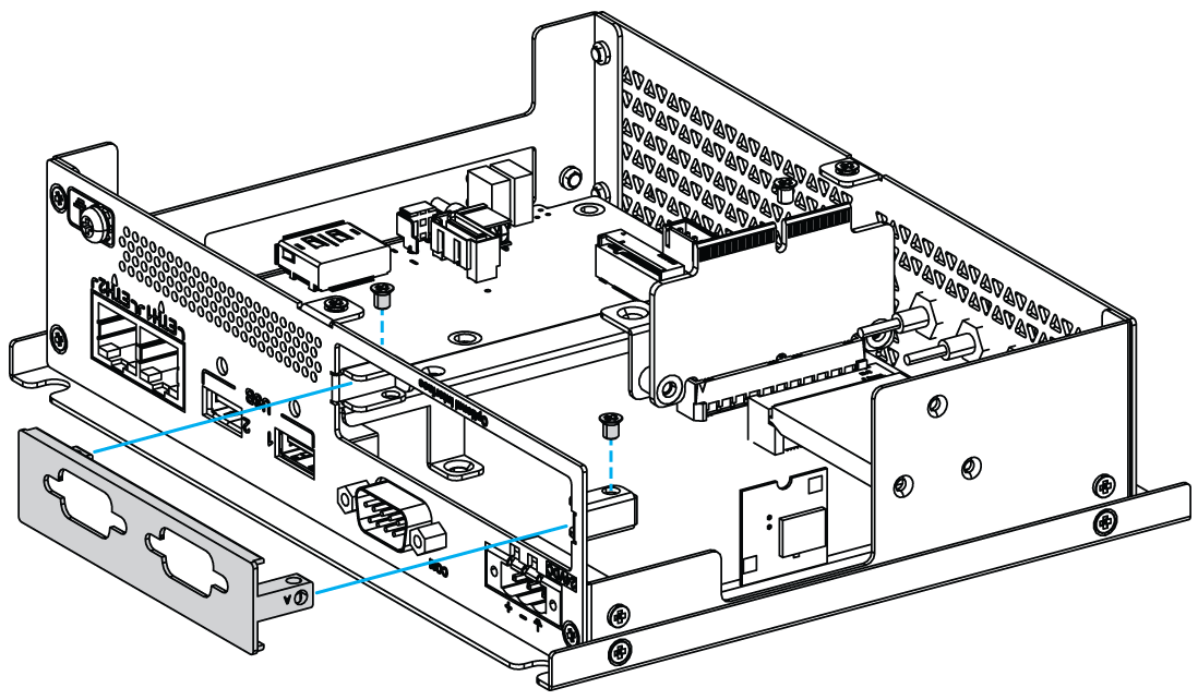
NOTE: The recommended torque to tighten these screws is 0.5 Nm (4.5 lb-in). |
|
5 |
Insert the mini PCIe card into the expansion card connector of the Box iPC Optimized and fasten it with two screws: 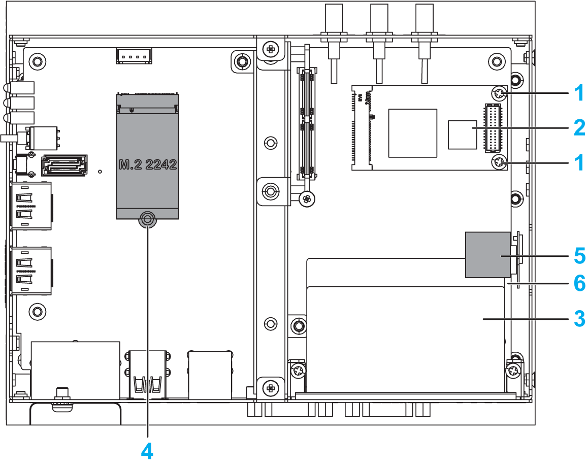
1 Screws size M2 (included in accessory Box iPC) 2 mini PCIe card 3 Optional interface 4 M.2 card for HMIBMO 5 TPM module 6 Pin header The pin headers are for both USB interface and Audio interface. NOTE: oWhen using a mini PCIe card with an external cable attached, install a clamp or other device to secure the cable. oThe requirement of Phillips screw driver is type size 2. The recommended torque to tighten these screws is 0.5 Nm (4.5 lb-in). |
|
6 |
Replace the covers and fasten them with eight screws: 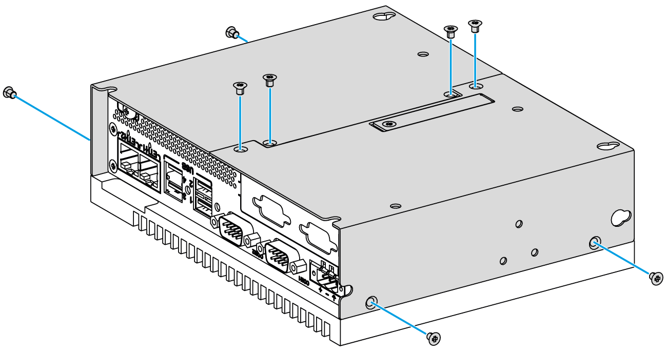
NOTE: The recommended torque to tighten these screws is 0.5 Nm (4.5 lb-in). |