Fast Transistor Outputs
Overview
The Modicon M241 Logic Controller has digital outputs embedded:
|
Reference |
Total number of digital outputs |
|||
|---|---|---|---|---|
|
TM241C••24R |
10 |
4 |
6 |
0 |
|
TM241C••24T TM241C••24U |
10 |
4 |
0 |
6 |
|
TM241C•40R |
16 |
4 |
12 |
0 |
|
TM241C•40T TM241C•40U |
16 |
4 |
0 |
12 |
|
(1) Fast transistor outputs which can be used as 100 kHz PTO outputs |
||||
For more information, refer to Output Management.
| DANGER | |
|---|---|
| WARNING | |
|---|---|
Fast Transistor Outputs Status LEDs
The following figure shows the status LEDs for the TM241C••24• controller (the TM241C•40• controllers are similar with 40 LEDs):

|
LED |
Color |
Status |
Description |
|---|---|---|---|
|
0...9 |
Green |
On |
The output channel is activated |
|
Off |
The output channel is deactivated |
Fast Transistor Outputs Characteristics
The following table describes the characteristics of the M241 Logic Controller fast transistor outputs:
|
Characteristic |
Value |
|||
|---|---|---|---|---|
|
TM241C•••R |
TM241C•••T |
TM241C•••U |
||
|
Number of fast transistor outputs |
4 outputs (TR0...TR3) |
4 outputs (Q0...Q3) |
||
|
Number of channel groups |
1 common line for TR0...TR3 |
1 common line for Q0...Q3 |
||
|
Output type |
Transistor |
|||
|
Logic type |
Source |
Source |
Sink |
|
|
Rated output voltage |
24 Vdc |
|||
|
Output voltage range |
19.2...28.8 Vdc |
|||
|
Rated output current |
0.1 A when configured for a fast function |
|||
|
0.5 A when used as a regular output |
||||
|
Leakage current |
Source |
≤ 0.3 mA |
||
|
Sink |
≤ 2 mA |
|||
|
Total output current per group |
2 A |
|||
|
Maximum power of filament lamp |
2.4 W max |
|||
|
Derating |
No Derating |
|||
|
Turn on time |
Max. 2 µs |
|||
|
Turn off time |
Max. 2 µs |
|||
|
Protection against short circuit |
Yes |
|||
|
Short circuit output peak current |
1.3 A max. |
|||
|
Automatic rearming after short circuit or overload |
Yes, 12 s |
|||
|
Protection against reverse polarity |
Yes |
|||
|
Clamping voltage |
Typically 39 Vdc +/- 1 Vdc |
|||
|
Maximum output frequency |
PTO |
100 kHz |
||
|
PWM |
20 kHz |
|||
|
PWM mode duty rate step |
0.1% at 20...1 kHz |
|||
|
Duty rate range |
1...99 % |
|||
|
Isolation |
Between output and internal logic |
500 Vac |
||
|
Between channel groups |
500 Vac |
|||
|
Connection type |
Removable screw terminal block |
|||
|
Connector insertion/removal durability |
Over 100 times |
|||
|
Cable |
Type |
Shielded, including 24 Vdc power supply |
||
|
Length |
Maximum 3 m (9.84 ft) |
|||
TM241C••24R / TM241C•40R Fast Transistor Outputs Wiring Diagrams
The following figure shows the connection of the fast transistor outputs:
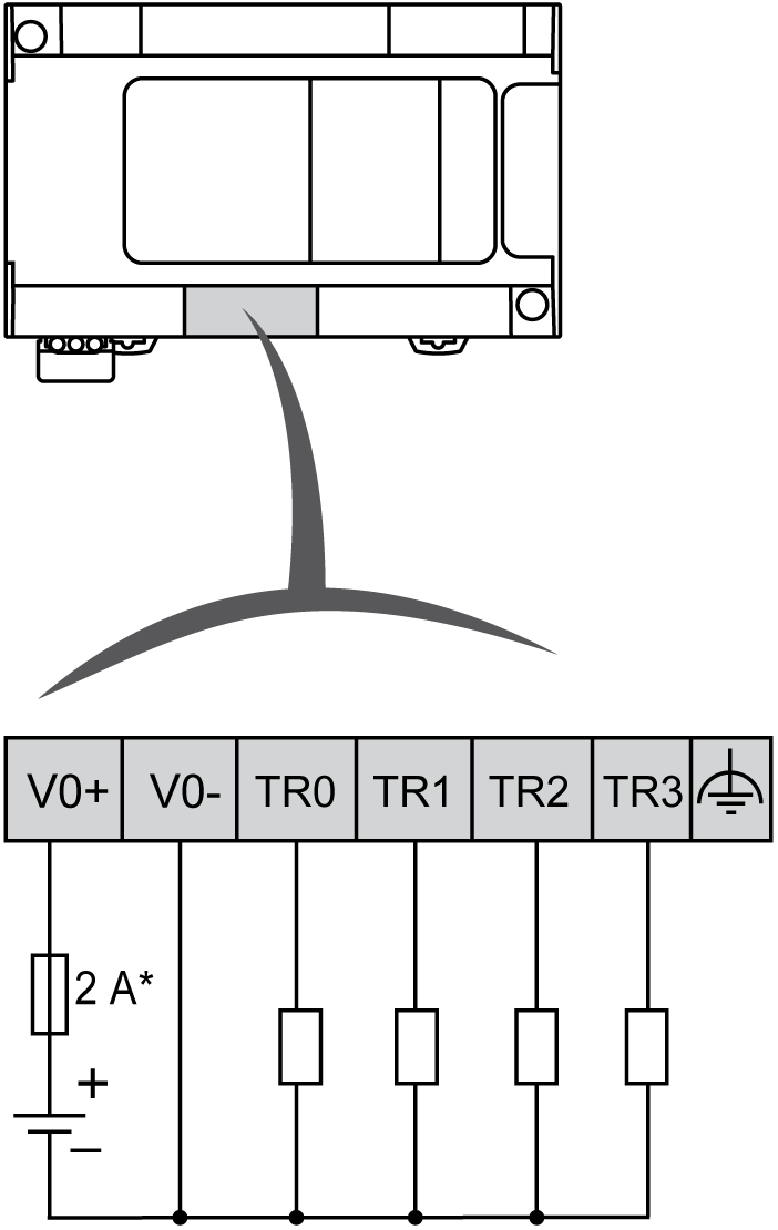
* 2 A fast-blow fuse
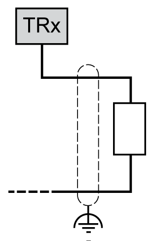
Fast output wiring for TR0... TR3:
| WARNING | |
|---|---|
TM241C••••T Fast Transistor Outputs Wiring Diagrams
The following figure shows the connection of the fast transistor outputs:
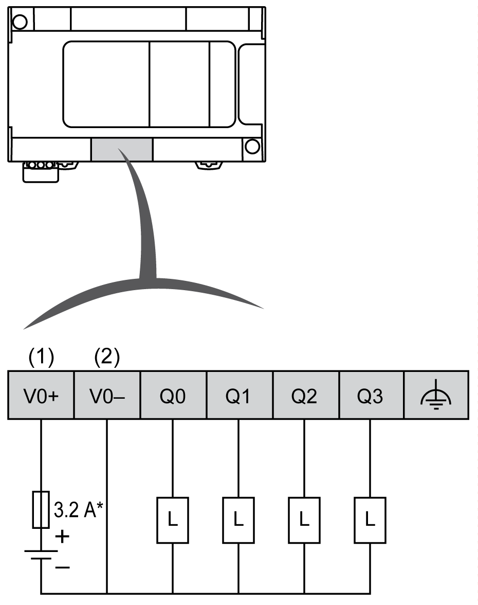
* Type T fuse
(1) The V0+, V1+, V2+ and V3+ terminals are not connected internally.
(2) The V0-, V1-, V2- and V3- terminals are not connected internally.
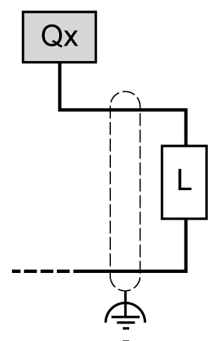
Fast output wiring for Q0... Q3:
| WARNING | |
|---|---|
TM241C••••U Fast Transistor Outputs Wiring Diagrams
The following figure shows the connection of the fast transistor outputs:
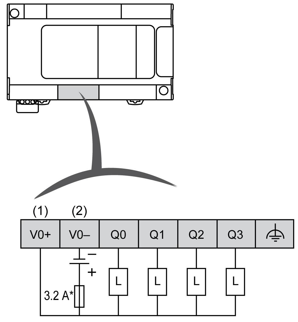
* Type T fuse
(1) The V0+, V1+, V2+ and V3+ terminals are not connected internally.
(2) The V0-, V1-, V2- and V3- terminals are not connected internally.
Fast output wiring for Q0... Q3:

| WARNING | |
|---|---|