Motion FB SF_SafeMotionControl
Short Description
The SF_SafeMotionControl function block acts as interface between the Safety Logic Controller and the safety logic of the drive (whether in the Safety Option Module of the ILM62 or the embedded safety functionality of the LXM62) which is the safety-related component of those drives.
|
The main purpose of the SF_SafeMotionControl function block is to request safety-related monitoring functions in the safety logic and to visualize the safety logic state. It performs the following tasks:
|
|
The drive to be monitored and controlled is identified via an axis ID which is to be applied at the S_AxisIN function block input as well as to the S_AxisOUT output. This way, a unique assignment between the function block and the physical axis is done.
The safety logic provides an internal start-up/restart inhibit that cannot be deactivated. The function block reflects this internal start-up/restart inhibit in the safety-related application programming and enables its resetting.
Supported Safety-related Functions
The following safety-related monitoring functions are supported by the SF_SafeMotionControl function block. Click the links to get detailed information.
The safety-related functions fulfill the safety requirements up to SIL3.
The various safety-related functions are subject to a fixed priority, whereby STO has the highest one.
Function Block Inputs
Click the corresponding hyperlinks to obtain detailed information on the items below.
|
Name |
Short description |
Value |
|---|---|---|
|
State-controlled input for activating the function block. Data type: BOOL Initial value: FALSE |
|
|
|
Input for specifying the axis to be controlled and monitored. Data type: SAFEDWORD Initial value: 0x0 |
This input must be connected to the SafeAxisIn data item provided (in the 'Devices' window) by the safety logic which is controlling the respective drive or axis. Therefore, its value is determined and provided by this safety logic. |
|
|
State-controlled input for requesting one of the safety-related monitoring functions. The * placeholder stands for: Data type: SAFEBOOL Initial value depends on the input:
NOTE:
As the SMS (Safe Maximum Speed) monitoring function is active at any time, no function block input is available/required to request it. However, a function block output for indicating its activity is provided. |
NOTE:
The S_STO_Request input must be connected.
NOTE:
For drive operation (rotation), SAFETRUE must apply to the S_STO_Request input. |
|
|
Edge-triggered input for the reset signal.
Data type: BOOL Initial value: FALSE
NOTE:
Resetting does not occur with a falling edge (TRUE > FALSE), as specified by standard EN ISO 13849-1, but with a rising edge (FALSE > TRUE). Refer to the hazard message below this table. |
|
Removing an active start-up/restart inhibit by means of a rising edge at the Reset input of the safety-related function block can directly cause the switching of outputs (depending on the states of the remaining inputs) and influence the speed and behavior of the axis to be controlled.
| WARNING | |
|---|---|
Function Block Outputs
Click the corresponding hyperlinks to obtain detailed information on the items below.
|
Name |
Short description |
Value |
|---|---|---|
|
Output for signaling "Function block activated/not activated". Data type: BOOL |
|
|
|
Output for indicating the controlled/monitored axis. Data type: SAFEDWORD |
This output must be connected to the SafeAxisOut data item provided (in the 'Devices' window) by the safety logic which is controlling the respective drive or axis. |
|
|
Outputs for signaling the status of a safety-related function. The * placeholder stands for: Data type: SAFEBOOL |
NOTE:
In case of an active start-up/restart inhibit, S_STO_SafetyActive = SAFETRUE and the other SafetyActive outputs are SAFEFALSE. |
|
|
Output for signaling that the STO safety-related function has been requested via the direct hard-wired signal link. Data type: SAFEBOOL
NOTE:
This output is only relevant if the |
|
|
|
Output for signaling the active ramp monitoring for the requested safety-related monitoring function(s). |
|
|
|
Output for signaling the overall status of the requested safety-related functions. Data type: SAFEBOOL |
|
|
|
Output for signaling the error state of the safety logic. Data type: SAFEBOOL |
|
|
|
Output for reporting the axis status. Data type: DWORD |
Bitwise status output as DWORD data type. Every Boolean FB output is mapped to one bit of this status DWORD which can be further processed and evaluated in the application (see table in topic "AxisStatus output"). |
|
|
Output for diagnostic message. Data type: WORD |
Diagnostic message of the function block. The possible values are listed and described in the topic "Diagnostic codes". |
Signal Sequence Diagram
This diagram relates to a sample application of the SF_SafeMotionControl FB: The states of two safety-related command devices, an emergency-stop control button and a key switch, are evaluated by the function block. The emergency-stop control button requests the STO function and the key switch requests the SLS1 function.
According to the example requirements, the axis speed must be reduced before personnel may enter the zone of operation. Only with reduced speed, for example, a safety door can be opened to grant access to the zone of operation without requesting the STO function.
The signal sequence diagrams in this documentation possibly omit particular diagnostic codes. For example, a diagnostic code is possibly not shown if the function block state is a temporary transition state and only active for one cycle of the Safety Logic Controller.
Only typical input signal combinations are illustrated. Other signal combinations are possible.
The signal sequence diagram is simplified and is intended to explain the functionality of the SF_SafeMotionControl function block. Therefore, this example is not intended as a practical solution implemented as shown and described in this document.
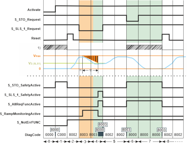
1) Internal startup/ restart inhibit
Also take the other signal sequence diagram into account.
|
0 |
The function block is not activated (Activate = FALSE). As a result, the outputs are FALSE/SAFEFALSE. |
|
1 |
After starting up, the safety logic automatically enters the STO defined safe-state(8000). After its activation (by switching Activate = TRUE), the function block indicates this state by S_STO_SafetyActive = SAFETRUE. As a consequence of the STO state, the internal start-up inhibit is active. (According to the relevant IEC 60204-1 standard, the STO function executes stop category 0. This stop category implies a subsequent start-up inhibit.) With the block activation, the S_NotErrFUNC output switches to SAFETRUE indicating that the function block has not detected any error. Then, the FB automatically transitions to the error state C000. During C000 (indicated by S_NotErrFUNC = SAFEFALSE), the STO state is maintained. |
|
2 |
With the FALSE > TRUE edge at the Reset input of the safety-related function block, the start-up/restart inhibit is removed. With this reset, the STO state is terminated. As no safety-related function is now requested, the S_STO_SafetyActive output switches back to SAFEFALSE while the other function block outputs keep their previous states. On that condition, the standard (non-safety-related) controller can start the drive operation by accelerating the axis to the target speed parameterized in the standard (non-safety-related) motion application. |
|
3 |
The SLS1 safety-related function is requested: The signal at the S_SLS_1_Request input switches to SAFEFALSE, for example, by unlocking a key switch.
Within the t1 time interval, the standard (non-safety-related) controller also receives the request from the connected process and initiates the motion control function according to the logic and drive parameterization defined in the standard (non-safety-related) application. t1 is to be defined in the safety logic device parameters ( After t1 has elapsed, the deceleration of the drive to target speed V2 is executed by the standard (non-safety-related) controller according to the drive parameterization defined in the standard application.
During the deceleration (ramp-down) phase t2, ramp monitoring is parameterized in our example for the SLS1 safety-related function. For that purpose, the corresponding safety logic parameter |
|
4 |
The parameterized limited target speed V2 (set with the This means the requested SLS1 safety-related function is activated correctly and the function block does not detect any error (S_NotErrFUNC remains SAFETRUE). As a result, S_SLS_1_SafetyActive switches to SAFETRUE when t2 elapses, indicating that SLS1 has entered its defined safe-state. Then, for the example, the safety door can be opened and access to the zone of operation is possible without a subsequent emergency stop. S_AllReqFuncActive simultaneously switches to SAFETRUE signaling that each requested safety-related function is activated correctly and as parameterized. As long as the request for the safety-related function is maintained by further applying SAFEFALSE to the S_SLS_1_Request input, the target speed V2 is monitored. Any exceeding of the target speed V2 results in the immediate request of the STO function and switches S_SLS_1_SafetyActive to SAFEFALSE. |
|
5 |
The request for the SLS1 safety-related function is removed by switching the signal at the S_SLS_1_Request input back to SAFETRUE (for example by locking the key switch after closing a safety door). The outputs S_SLS_1_SafetyActive and S_AllReqFuncActive directly switch back to SAFEFALSE, thus signaling that no safety-related function is active anymore. As no restart inhibit is required following the SLS function, the standard (non-safety-related) controller can accelerate the axis without any reset signal as soon as the request for the safety-related function is removed at S_SLS_1_Request. The axis achieves the speed (parameterized in the standard (non-safety-related) motion application) without exceeding the defined and permanently monitored safe maximum speed (Vmax). |
|
6 |
The STO safety-related function is requested: By pressing the monitored emergency-stop control button, the signal at the S_STO_Request input switches to SAFEFALSE. As a result, the safety logic directly sets the drive torque-free and the axis coasts down. S_STO_SafetyActive switches to SAFETRUE, indicating that STO is activated. As STO is the only requested safety-related function at that time, S_AllReqFuncActive also shows SAFETRUE. |
|
7 |
The request for the STO function is removed by unlocking the emergency-stop control button before the axis has reached the standstill. As a result, the signal from the emergency stop button, connected to the S_STO_Request input, switches back to SAFETRUE. The drive, however, remains torque-free due to the implemented restart inhibit and the axis keeps on coasting down until v = 0. S_STO_SafetyActive and S_AllReqFuncActive remain SAFETRUE as long as the restart inhibit is active. |
|
8 |
With the FALSE > TRUE edge at the Reset input of the safety-related function block, the restart inhibit is removed. As no safety-related function is requested, the standard (non-safety-related) controller can accelerate the axis until it achieves its programmed speed (parameterized in the standard (non-safety-related) motion application) without exceeding the defined and permanently monitored safe maximum speed (Vmax). |
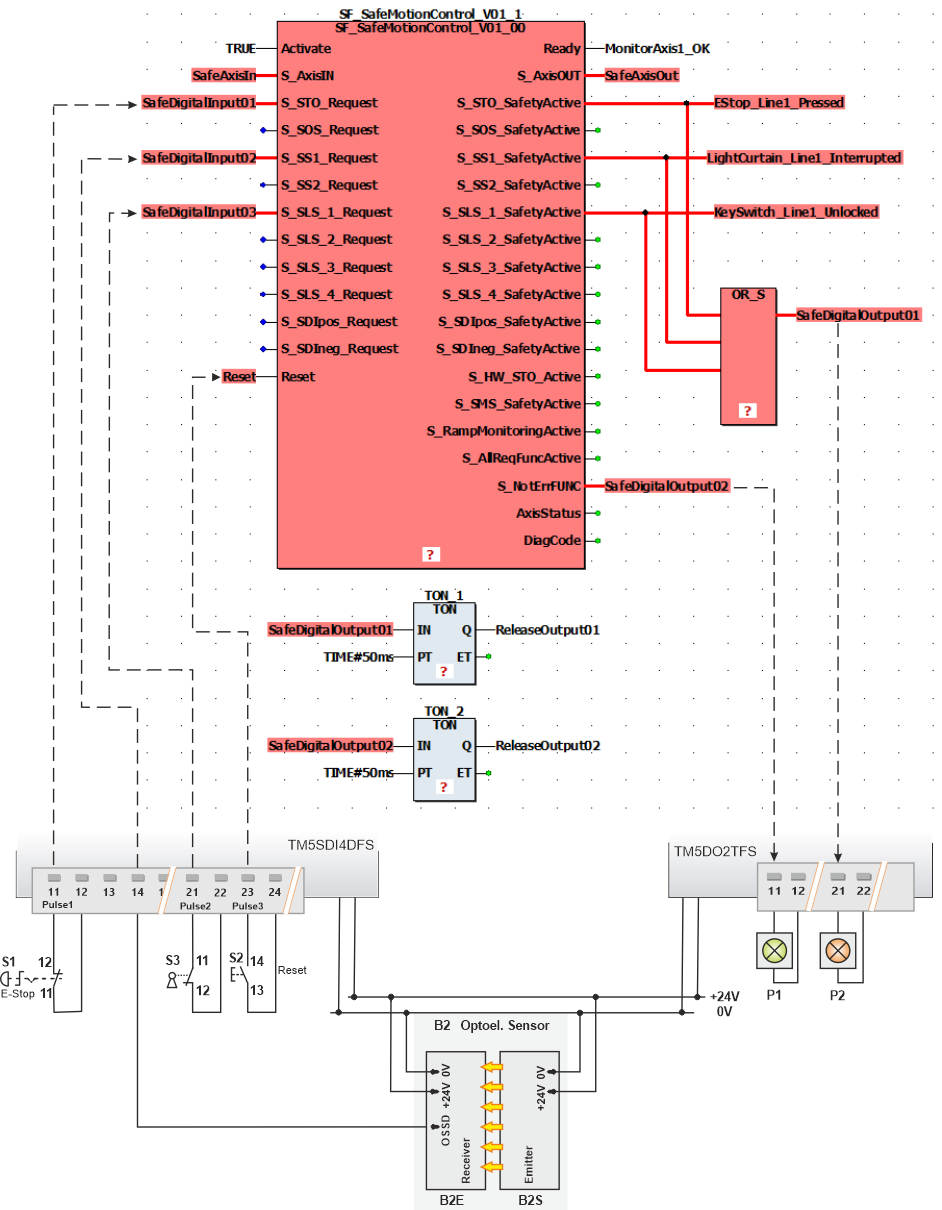
Application Example
In the example shown below, the Safety Logic Controller processes the input signals coming from a TM5 safety-related extension module. Here, an emergency-stop control button, a key switch and a light curtain are connected. These devices are connected via global I/O variables to the respective function block request inputs.
At the safety-related output device two signal lamps are connected: The green lamp signals "Safety Module OK" and the red one indicates "Safety-related function requested".
Also take the details on this application example and the accompanying notes into account.
Only you, the user, machine builder or system integrator can be aware of all the conditions and factors realized in the design of your application for the machine. Therefore, only you can determine the automation equipment and the related safeties and interlocks which can be properly used, and validate such usage.
| WARNING | |
|---|---|
The application example is simplified and is intended to explain the functionality of the SF_SafeMotionControl function block. Therefore, this example is not intended as a practical solution implemented as shown and described in this document.
Detailed Information
Additional information is available in the following sections: