Mounting
How to Mount the Lexium 62 Power Supply, Lexium 62 Servo Drive and Lexium 62 DC Link Support Module
|
Step |
Action |
|---|---|
|
1 |
Remove the terminal covers on the module sides (Lexium 62 Power Supply, Lexium 62 Servo Drive and Lexium 62 DC Link Support Module) on which the modules are connected with each other. For this purpose, press the screwdriver in the opening (1) (blade width: 5.5...8 mm (0.22...0.31 in)) on the top side of the module to loosen the terminal cover. 
|
|
2 |
Then remove the terminal covers (a,b) toward the outside. |
|
3 |
Screw the pan-head screws M6 (socket head cap screws) into the prepared mounting holes. |
|
4 |
Keep a distance of 10 mm (0.39 in) between the screw head and the mounting plate. |
|
5 |
Hook in device and verify the vertical mounting arrangement. |
|
6 |
If using Lexium 62 DC Link Support Module, then place it on the left or the right end of the row of Lexium 62 devices. Place the Power Supply and the Drive Modules in the following order from left to right according to the current carrying capacity:
NOTE: By doing this, the load on the DC bus- and 24 V-supply at the wiring bus is reduced.
|
|
7 |
Tighten the mounting screws (torque: 4.6 Nm (41 lbf in)). |
How to Assemble the Modules
|
Step |
Action |
|---|---|
|
1 |
Verify whether the slide on the Bus Bar Module can be moved easily. If not, loosen the screws securing the slide to the Bus Bar Module. |
|
2 |
Connect devices via the slide of the Bus Bar Module (1). 
|
|
3 |
Tighten the screws of the Bus Bar Module (torque: 2.5 Nm / 22 lbf in). |
|
4 |
Mount the terminal covers left TOP (a) and right TOP (b) on the outside of the Bus Bar Module combination. For important safety information, follow the instructions in the safety message after this table. Shock terminal covers on the outside of the Bus Bar Module combination 
|
This product has a touch current greater than 3.5 mA. If the protective earth ground connection is interrupted, a hazardous touch current may flow if the housing is touched.
| DANGER | |
|---|---|
How to Ground the Lexium 62 Power Supply
|
Step |
Action |
|---|---|
|
1 |
Connect the additional protective earth ground conductor with the ring cable lug and the M5 screw to the heat sink of the power supply (tightening torque: 3.5 Nm (31 lbf in)). |
|
2 |
Follow the assembly based on the heat sink:
|
|
3 |
Connect the plug-in connector 24 V supply to the power supply.
NOTE: See important hazard message after the table.
|
|
4 |
Connect the plug-in connector AC supply to the power supply. |
|
5 |
Connect the Sercos cable () to the power supply. |
| DANGER | |
|---|---|
How to Connect the Modules
|
Step |
Action |
|---|---|
|
1 |
Insert the Sercos cable CN2 (CN3) into the drive module.
NOTE: Depending on the device combination, choose the appropriate Sercos cable length.
NOTE: If possible, establish a Sercos connection via the ring topology (2).
NOTE: If Sercos devices are assigned via the topological addresses ( = ) to the PacDrive LMC, then consider the following:
Line topology and ring topology 
1 Line topology 2 Ring topology |
|
2 |
Connect the plug-in connector CN4 "Ready relay output" to the power supply. |
|
3 |
Connect the plug-in connector CN6 / CN11 "Inverter Enable" to the drive module (Lexium 62 Servo Drive). |
|
4 |
Optionally, connect the plug-in connector CN4 "IO" to the drive module. |
|
5 |
Optionally, connect the plug-in connector CN5 "IO voltage supply" to the drive module. |
|
6 |
Connect the "Motor connector Axis A" CN8 to the drive module. |
|
7 |
|
|
8 |
Connect the "Encoder plug-in Axis A" CN7 to the drive module. |
|
9 |
Connect the "Encoder plug-in Axis B or Machine Encoder" CN9 to the double drive, if available. |
|
10 |
Connect the "Encoder output plug" CN12 to the advanced drive, if available. |
How to Assemble the Lexium 62 DC Link Terminal
To assemble the optional Lexium 62 DC Link Terminal, proceed as follows:
|
Step |
Action |
|---|---|
|
1 |
Mount the strain relief (1) to the control cabinet wall using two M5 screws. 
|
|
2 |
Remove insulation of wires and apply cable end (without insulating sleeve) to flexible wires. |
|
3 |
Insert the protective earth ground wire into the green/yellow terminal (2) and tighten the clamping screw (3) (torque: 4.5 Nm / 39.8 lbf in). 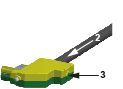
|
|
4 |
Insert the other 4 wires (DC- and DC+ wires to the black terminals, 24 V, and 0 V wires to the blue terminals) and tighten the clamping screws (torque: 4.5 Nm / 39.8 lbf in).
NOTE: The terminals are not connected to the Bus Bar Module yet.
For important safety information, follow the instructions in the safety messages after this table. |
|
5 |
Plug in the terminals with the wires to the Bus Bar Module connectors in the correct order (top to bottom). (4). 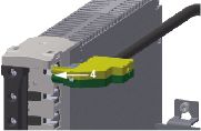
|
|
6 |
Clip on the retaining bracket (5) to the Bus Bar Module. 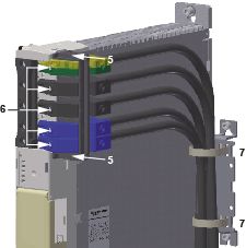
NOTE: The retaining bracket is securely seated when you hear it click.
Result: The terminals are secured against twisting. |
|
7 |
Tighten the screws of the terminals (6 in the graphic presented in step 6) on the Bus Bar Module (torque: 2.5 Nm / 22 lbf in). |
|
8 |
Secure the five wires on the strain relief by using cable ties (7 in the graphic presented in step 6).
NOTE: If using single-core wires within one cabinet, you must conform to the following wiring rules:
|
|
9 |
Optionally: If you couple two control cabinets, ground the cable shield by using the strain relief in combination with a shield connection terminal block (8) (Icotec SKS 20-35 or Phoenix Contact SK35).
NOTE: A shield connection terminal block can be used for cables with diameters between 20 mm (0.79 in) and 35 mm (1.37 in).
|
| DANGER | |
|---|---|
| DANGER | |
|---|---|
| DANGER | |
|---|---|
| DANGER | |
|---|---|
| DANGER | |
|---|---|
| DANGER | |
|---|---|
| WARNING | |
|---|---|
Device Combination and Sercos Cable Length
The table shows the Sercos cable length to wire of the Sercos communication for each device combination:
|
Connection |
Device left side |
Device right side |
Sercos cable length |
|---|---|---|---|
|
CN2 / CN3 |
LXM62PD20 / LXM62PD84 |
LXM62PD20 / LXM62PD84 |
130 mm (5.11 in) |
|
CN2 / CN3 |
LXM62PD20 / LXM62PD84 |
LXM62DD / LXM62DU |
130 mm (5.11 in) |
|
CN2 / CN3 |
LXM62PD20 / LXM62PD84 |
LXM62DC13C / LXM62DC13E |
150 mm (5.90 in) |
|
CN2 / CN3 |
LXM62DC13C / LXM62DC13E |
LXM62DC13C / LXM62DC13E |
130 mm (5.11 in) |
|
CN2 / CN3 |
LXM62DC13C / LXM62DC13E |
LXM62PD20 / LXM62PD84 |
115 mm (4.52 in) |
|
CN2 / CN3 |
LXM62DC13C / LXM62DC13E |
LXM62DD / LXM62DU |
115 mm (4.52 in) |
|
CN2 / CN3 |
LXM62DD / LXM62DU |
LXM62DD / LXM62DU |
90 mm (3.54 in) |
|
CN2 / CN3 |
LXM62DD / LXM62DU |
LXM62PD20 / LXM62PD84 |
90 mm (3.54 in) |
|
CN2 / CN3 |
LXM62DD / LXM62DU |
LXM62DC13C / LXM62DC13E |
115 mm (4.52 in) |