TM251MESC Presentation
Description
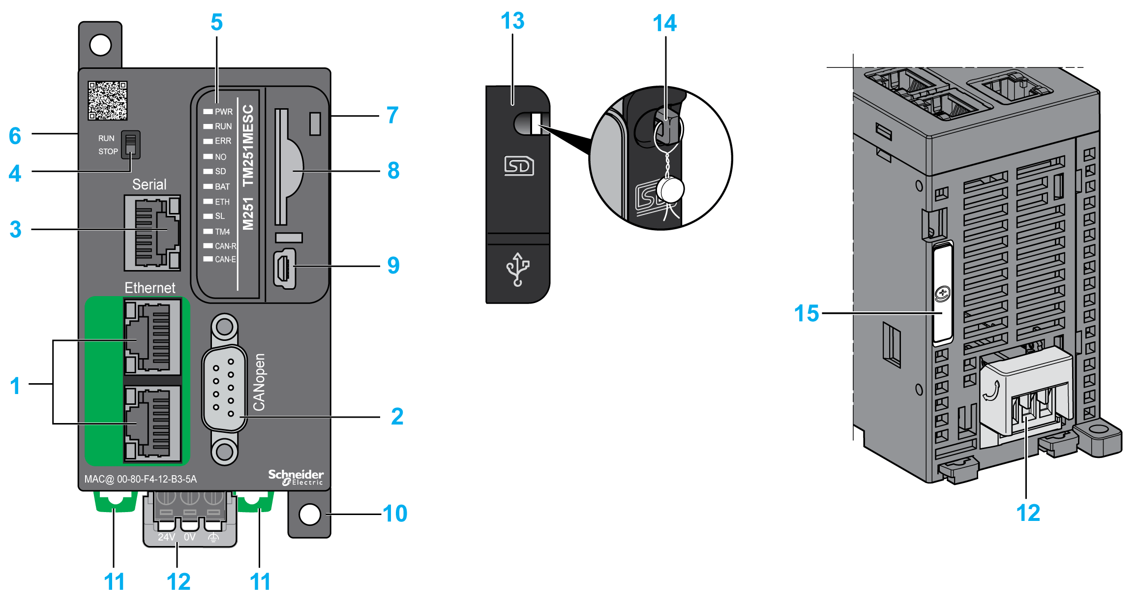
This figure shows the different components of the TM251MESC logic controller:

|
N° |
Description |
Refer to |
|---|---|---|
|
1 |
Dual port Ethernet switch |
|
|
2 |
CANopen port |
|
|
3 |
Serial line port / Type RJ45 (RS-232 or RS-485) |
|
|
4 |
Run/Stop switch |
|
|
5 |
Status LEDs |
|
|
6 |
TM4 bus connector |
|
|
7 |
TM3/TM2 bus connector |
|
|
8 |
SD card slot |
|
|
9 |
USB mini-B programming port / For terminal connection to a programming PC (EcoStruxure Machine Expert) |
|
|
10 |
Surface mounting lugs |
– |
|
11 |
Clip-on lock for 35 mm (1.38 in.) top hat section rail (DIN-rail) |
|
|
12 |
24 Vdc power supply |
|
|
13 |
Protective cover (SD card slot and USB mini-B programming port) |
– |
|
14 |
Locking hook (Hook not included) |
– |
|
15 |
Battery holder |
Status LEDs
This figure shows the status LEDs:

The following table describes the system status LEDs:
|
Label |
Function Type |
Color |
Status |
Description |
||
|---|---|---|---|---|---|---|
|
PWR |
Power |
Green |
On |
Indicates that power is applied. |
||
|
Off |
Indicates that power is removed. |
|||||
|
RUN |
Machine status |
Green |
On |
Indicates that the controller is running a valid application. |
||
|
Flashing |
Indicates that the controller has a valid application that is stopped. |
|||||
|
1 flash |
Indicates that the controller has paused at BREAKPOINT. |
|||||
|
Off |
Indicates that the controller is not programmed |
|||||
|
ERR |
Internal Error |
Red |
On |
Indicates that an operating system error has been detected |
||
|
Fast flashing |
Indicates that the controller has detected an internal error |
|||||
|
Slow flashing |
Indicates either that a minor error has been detected if RUN is ON or that no application has been detected |
|||||
|
I/O |
I/O error |
Red |
On |
Indicates device errors on the serial line, SD card, TM4 bus, TM3 bus, Ethernet port(s) or CANopen port. |
||
|
SD |
SD card access |
Green |
On |
Indicates that the SD card is being accessed |
||
|
BAT |
Battery |
Red |
On |
Indicates that the battery needs to be replaced. |
||
|
Flashing |
Indicates that the battery charge is low. |
|||||
|
ETH |
Ethernet port status |
Green |
On |
Indicates that the ethernet port is connected and the IP address is defined. |
||
|
3 flashes |
Indicates that the ethernet port is not connected. |
|||||
|
4 flashes |
Indicates that the IP address is already in used. |
|||||
|
5 flashes |
Indicates that the module is waiting for BOOTP or DHCP sequence. |
|||||
|
6 flashes |
Indicates that the configured IP address is not valid. |
|||||
|
SL |
Serial line |
Green |
Flashing |
Indicates the status of serial line |
||
|
Off |
Indicates no serial communication |
|||||
|
TM4 |
Error on TM4 bus |
Red |
On |
Indicates that an error has been detected on the TM4 bus |
||
|
Off |
Indicates that no error has been detected on the TM4 bus |
|||||
|
CAN-R |
CANopen running status |
Green |
On |
Indicates that the CANopen bus is operational. |
||
|
Off |
Indicates that the CANopen master is configured. |
|||||
|
Flashing |
Indicates that the CANopen bus is being initialized. |
|||||
|
1 flash per second |
Indicates that the CANopen bus is stopped. |
|||||
|
CAN-E |
CANopen error |
Red |
On |
Indicates that the CANopen bus is stopped (BUS OFF). |
||
|
Off |
Indicates no CANopen detected error. |
|||||
|
Flashing |
Indicates that the CANopen bus is not valid. |
|||||
|
1 flash per second |
Indicates that the controller has detected that the maximum number of error frames has been reached or exceeded. |
|||||
|
2 flashes per second |
Indicates that the controller has detected either a Node Guarding or a Heartbeat event. |
|||||
