Configuring Ethernet connections
This section only applies if your meter has the Ethernet option. Refer to the ION8650 Installation Guide for Ethernet port specifications and information on determining the options available on your meter.
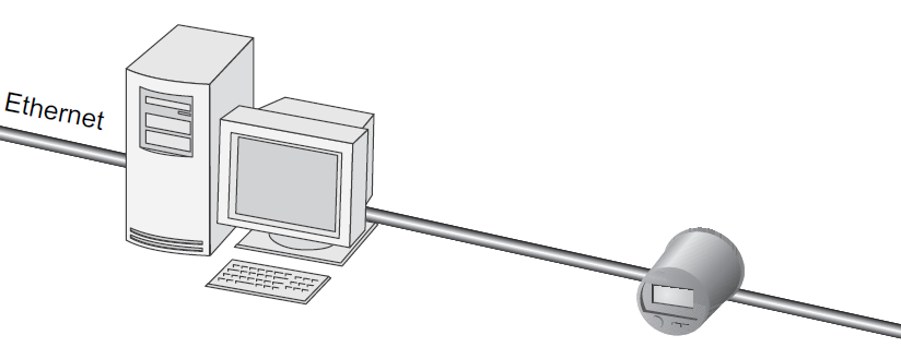
Ethernet connections are made via the RJ45 modular jack on the rear of the unit. Use high quality Category 3, 4 or 5 UTP cable (RJ45 female to RJ45 male) if you require an extension. The optional Ethernet port is capable of data rates up to 10 Mbps and supports TCP/IP, FTP, ION, and Modbus/TCP protocols. The meter supports a maximum of eight simultaneous Ethernet connections with additional dedicated connections for Modbus master over TCP/IP and IEC 61850.
NOTE: Some features, such as IEC 61850, COMTRADE and Ethernet outage notification, require that your meter has an Ethernet connection.
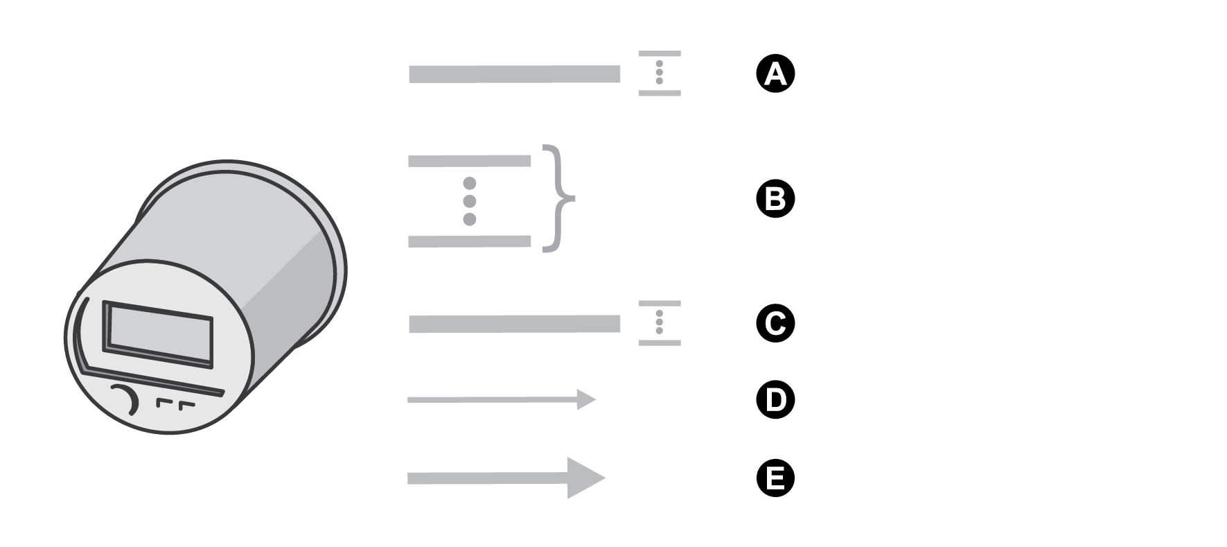
|
A |
TCP/IP Modbus master dedicated TCP connection. Connect with up to 10 Modbus slave IP addresses. Refer to Third party protocols |
|
B |
8 simultaneous connections. Protocols include ION, DNP, and Modbus/TCP. |
|
C |
IEC 61850 dedicated connection for up to 5 IEC 61850 clients. |
|
D |
1 FTP connection. |
|
E |
SMTP server (email), outgoing only. |
You can configure Ethernet communications using the front panel, Power Monitoring Expert or ION Setup. In each case, you must configure the IP Address, Subnet Mask, Gateway, SMTP Server and SMTP Connection Timeout to properly match your system. You must also ensure that the network ports are either enabled or disabled, depending on your system configuration.
NOTE: The MAC address of your meter cannot be changed and is provided for information only.
Using the front panel
- Press and hold the ALT/ENTER button for a few seconds. The SETUP menu appears.
- Use the up or down arrow buttons to select NETWORK SETUP and press ALT/ ENTER.
- Configure the Ethernet Communications settings (for example, IP Address, Mask, Gateway, SMTP Address and Port Enable) to match your communications system.
Using ION Setup
- Open the Setup Assistant for your meter. See the ION Setup Help for instructions.
- Select Communications > Basic Ethernet and click the IPv4 and TCP/IP tabs.
- Select a setting and then click Edit. Configure the settings as required.
| Parameter | Values | Description |
|---|---|---|
| IPv4 Address | Contact your local network administrator for parameter values. | Specifies TCP/IP Ethernet address. |
| Subnet Mask | Contact your local network administrator for parameter values. | The subnet IP address of your network. |
| Default Gateway | Contact your local network administrator for parameter values. | The gateway IP address of your network. |
| Rx Timeout | Contact your local network administrator for parameter values. | Specifies the number of seconds the meter will wait for communication acknowledgments. |
| Modbus Gateway | 7801, 7802, 502 | Specifies the port on which the Modbus Gateway will send and receive requests. |
| MAC Address | Read-only |
Your meter’s media access control (MAC) address. |
- Select Communications > Advanced Ethernet and click the DNS and SMTP tabs.
- Select a setting and then click Edit. Configure the settings as required
| Parameter | Values | Description |
|---|---|---|
| Primary DNS | Contact your local network administrator for parameter values. | The IP address of your network’s primary DNS server, if your network uses DNS. |
| Secondary DNS | Contact your local network administrator for parameter values. | The IP address of your network’s primary DNS server, if your network uses DNS. |
| SMTP Server | Contact your local network administrator for parameter values. | The IP address of your SMTP server. |
| SMTP Connection Timeout | Contact your local network administrator for parameter values. | Specifies the number of seconds the meter will wait for communication from the SMTP server. |
Using Power Monitoring Expert
After you wire your meter to the Ethernet network and perform basic setup, add the meter to your Power Monitoring Expert network using Management Console.
To enable communications through the Ethernet port, you must configure the Ethernet Communications module. Start Designer and configure the IP Address, Subnet Mask, Gateway, SMTP Server and SMTP Connection Timeout registers to match your system.
Adding an Ethernet device to your Power Monitoring Expert network
In Management Console, the Ethernet Device Options screen appears when you add an Ethernet device (meter). Use this screen to describe your meter’s Ethernet address and other communications information. Be sure to include:
- the server computer that communicates with the Ethernet device.
- the Ethernet device TCP/IP address.
Domain name resolution (DNS)
You can configure the meter as a DNS client in systems using a DNS server.
A DNS server maps domain names to IP addresses. If you configure the meter to use a DNS server, the meter can communicate with other network resources using their domain names, rather than their IP addresses, and vice versa. For example, if your network has an SMTP server with the domain name of smtp.company.com, you can enter smtp.company.com as the SMTP Server address in the meter’s communications settings.
Configuring EtherGate connections
The meter can function as an Ethernet gateway (EtherGate). EtherGate is a powerful communications tool that lets you communicate through a gateway meter to a serial network connected to the meter. When a meter installed on the Ethernet network has EtherGate enabled, a master device (such as a workstation running Power Monitoring Expert) can communicate through the gateway meter to a serial network of devices wired to the gateway meter’s COM port. The transfer of data between protocols is handled automatically. EtherGate is available on serial ports COM1 and COM4 in place of the ION, Modbus Master, Modbus RTU, or DNP 3.00 protocols. With EtherGate enabled, the meter permits the direct transfer of data from up to 62 devices (31 devices per COM port).
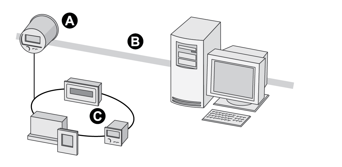
|
A |
Gateway meter |
|
B |
Ethernet |
|
C |
Serial devices connected to the gateway meter |
Install the serial devices, configure them and connect them to your Ethernet-connected gateway meter. Ensure that each serial device is configured with the same baud rate and has a unique Unit ID. Then use the meter’s front panel, Power Monitoring Expert or ION Setup to change the COM1 or COM4 Protocol setting to EtherGate. You must then create an EtherGate site in Power Monitoring Expert or ION Setup and add the serial devices to the EtherGate site. See The ION meter as an Ethernet gateway technical note for more information on setting up an Ethernet gateway.
Using the front panel to set the EtherGate protocol
- Press and hold the ALT/ENTER button for a few seconds. The SETUP menu appears.
- Use the up or down arrow buttons to select the COM port that you want to configure (COM1 or COM4) and press ALT/ENTER.
- Scroll to PROTOCOL and press ALT/ENTER. Change the port’s PROTOCOL setting to ETHERGATE.
- Press ALT/ENTER to set the protocol.
Using ION Setup to create an EtherGate site
Follow the instructions below to communicate to the devices on the RS-485 loop with ION Setup.
In ION Setup:
- Right-click on your workstation icon and select Insert Item. The New Network Item dialog box appears.
- Select Site and click OK. The New Site dialog box appears.
- Click the General tab.
- Configure the site as follows:
- Type a site name.
- Select Ethernet from the Comm Link options.
- Select the Gateway check box.
- Type the meter’s IP address and select a port in the Gateway Info fields. For the port, select either 7801 for COM1 or 7802 for COM4.
Click OK.
- Right-click on your newly created site and select Insert Item. The New Network Item dialog box appears.
- Select Meter and click OK. The New Device dialog box appears.
- Enter serial device information here and click OK. Your new device appears under your newly created site.
- Repeat steps 5 to 7 to enter each device on your serial network.
NOTE: Use a standard Ethernet connection in ION Setup to connect to and read data from your EtherGate meter.
Using Power Monitoring Expert to create an EtherGate site
Follow the instructions below to communicate to the devices on the RS-485 loop with Power Monitoring Expert.
In Management Console:
- Create an Ethernet gateway site.
- Configure your Ethernet gateway site with the IP address of the gateway meter. Select the IP Port that matches the gateway meter’s COM port that is connected to the RS-485 loop (select 7801 for COM1 or 7802 for COM4).
- Add each of the devices on the RS-485 loop to the Ethernet Gateway site (you do not need to add the gateway meter as a device).
NOTE: Use a standard Ethernet connection in Power Monitoring Expert to connect to and read data from your EtherGate meter.
Enabling and Disabling Ethernet ports
Through the front panel, you can enable or disable the Ethernet ports on your meter.
Changing Ethernet configuration parameters without another method of configuration enabled may cause loss of communications with your device.
notice
data Loss
Maintain sufficient access to communicate to and configure your device.
Failure to follow these instructions can result in data loss.
Follow the instructions below to enable and disable the Ethernet ports on your meter. Using the front panel:
- Press and hold the ALT/ENTER button for a few seconds. The SETUP menu appears.
- Use the up or down arrow buttons to select NETWORK SETUP and press ALT/ ENTER.
- Scroll to PORT ENABLE and press ALT/ENTER.
- Select the port you want to change, and press ALT/ENTER. Select Yes to enable the port and No to disable.
- Select YES to confirm the change. Enter the meter password if prompted.
Using ION Setup
See Ethernet protocol control for instructions regarding enabling and disabling Ethernet ports through ION Setup.
Meter FTP server
The meter can function as an FTP server, supporting IEC 61850 protocols, COMTRADE formatted waveform files and TLS certificates. The FTP timeout period is 90 seconds on a control port. Only one simultaneous FTP transfer connection is permitted. To connect to your meter, ensure that your FTP software is configured to only use a single FTP connection. The recommended FTP software is Windows Explorer or WinSCP running on a Windows-based machine.
NOTE: To connect to your meter using Windows Explorer, you must include the login and password in the FTP connection string. For example, with standard meter security (no user configured) and the front panel password of 2, to connect to a meter with an IP address of 123.45.6.78, the Windows Explorer connection string would be ftp:// 0:2@123.45.6.78.
The meter communicates using FTP on the following ports:
| Port | Description |
|---|---|
| 21 | Incoming commands connections |
| 20 | Active data connections |
| 3000-3020 | Passive data connections |
File names are limited to ASCII characters that do not contain a blank space or /, \, “, *, ?, <, >, and have a maximum length of 64 characters.
FTP folder structure
Your meter has the following FTP folder structure:
- CASTORE: you can add and delete TLS certificates in this folder.
- COMTRADE: you can read COMTRADE files from these folders, but you cannot delete or add files.
- IEC61850: you can add an IEC 61850 configuration (CID) file to this folder to activate the IEC 61850 protocol functions of your meter.
For more information about using FTP for IEC 61850 or COMTRADE, refer to the IEC 61850 protocol and ION Technology protocol document or the COMTRADE and ION Technology technical note.