Scroll Module
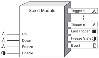
When linked to the Show inputs of Display Modules, a Scroll Module can determine the sequence and rate of scrolling of multiple front panel display screens.
Module icon
![]()
Overview
The Trigger output registers of the Scroll Module pulse in succession at a predetermined speed. The Scroll Module also allows you to temporarily freeze the scrolling action of the front panel display.

NOTE: The registers and settings available in this module depend on the device or node you are configuring, as well as its firmware and template versions. Not all registers or settings are available on all devices or the Virtual Processor, and labels may vary.
Inputs
 Up
Up
If the module is scrolling, a pulse to this input freezes scrolling. If the module is already frozen, the previous Trigger is pulsed and the freeze timer is reset.
The result of pulsing this input depends on the state of the Scroll Module’s Freeze State output register as follows:
- If the Freeze State output is off when a pulse is received, the Freeze State output turns on for the amount of time specified in the Freeze Time setup register.
- If the Freeze State is on when a pulse is received on the Up input, two events occur: first, a pulse is generated on the Trigger output register numbered one less than the number stored in the Last Trigger output register (if the last trigger that was pulsed was Trigger 1, the Trigger selected in the Wraparound setup register is pulsed); second, the freeze timer is reset to the duration specified in the Freeze Time setup register.
 Down
Down
If the module is scrolling, a pulse to this input freezes scrolling. If the module is already frozen, the next Trigger is pulsed and the freeze timer is reset.
The result of pulsing this input depends on the state of the Scroll Module’s Freeze State output register as follows:
- If the Freeze State output is off when a pulse is received, the Freeze State output turns on for the amount of time specified in the Freeze Time setup register.
- If the Freeze State is on when a pulse is received, two events occur: first, a pulse is generated on the output Trigger numbered one more than the number stored in the Last Trigger output register (if the Last Trigger output register contains the Trigger selected in the Wraparound setup register, then Trigger 1 is pulsed); second, the freeze timer is reset to the duration specified in the Freeze Time setup register.
 Freeze
The effect of a pulse arriving on the Freeze input is dependent upon the Scroll Module’s Freeze State output register as follows:
- If the Freeze State output is off when a pulse is received on the Freeze input, the Freeze State output turns on for the amount of time specified in the Freeze Time setup register.
- If the Freeze State is on when a pulse is received on the Freeze input, the display remains frozen for the entire duration specified in the Freeze Time setup register (i.e. the “freeze timer” is reset).
 Enable
This input enables or disables the module’s inputs. When the Enable input is off, the module does not respond to any other inputs; no pulses are generated on the Trigger outputs, and the Freeze State is set to off. When the Enable input changes from off to on, the module pulses its Trigger outputs in sequence, starting at the first Trigger. The Scroll module is enabled by default.
Setup registers
 Scroll Delay
This register contains the time (in seconds) that will elapse between successive pulses on the Trigger outputs when the Scroll Module is enabled.
 Wraparound
This register contains the number of one of the Trigger outputs (for example, Trigger 3). When this Trigger is pulsed, the Scroll Module will return to the first Trigger (i.e. Trigger 1). For example, if the Wraparound is 3, the Trigger outputs will be pulsed in the following order: Trigger 1, Trigger 2, Trigger 3, Trigger 1, Trigger 2, etc. Generally, the number of Trigger outputs used by the Scroll Module is entered here.
 Freeze Time
This register contains the time (in seconds) that the Scroll Module will remain “frozen”. The module becomes frozen when a pulse has been received on the Freeze, Up, or Down inputs. After the module has become frozen, any further pulses on the Freeze, Up or Down inputs will have the effect of resetting the timer that counts down the Freeze Time in seconds.
Output registers
 Trigger 1 – n
These output registers are pulsed in sequence by the Scroll Module. Up to 40 Trigger outputs can be linked.
 Last Trigger
This numeric register contains the number of the last pulsed Trigger.
 Freeze State
When this register is on, the module is in the frozen state; scrolling will not commence for the duration specified in the Freeze Time setup register.
 Event
Event
All events are recorded in the Event register.
Possible events and their associated priority numbers are:
| Event priority group | Priority | Description |
|---|---|---|
| Setup Change | 10 | Input links, setup registers or labels have changed. |
The Event output register stores the following information for each ION event: time stamp, priority, cause, effect, and any values or conditions associated with the cause and effect.
Responses to special conditions
The following table summarizes how the module behaves under different conditions.
| Condition | Response of output registers |
|---|---|
| The device is powered up | All numeric and Boolean outputs are not available. |
| The module is disabled | All numeric and Boolean outputs are not available. |
| Any changes to setup registers | All numeric and Boolean outputs are not available. |
Detailed module operation
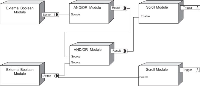
If two Scroll Modules are active at the same time, then the results of the front panel display become unpredictable. The default framework uses AND/OR Modules to ensure that no two Scroll Modules are enabled at the same time. You should use a similar strategy when creating custom links with more than one Scroll Module; see the following example.
The External Boolean Modules are the front panel buttons that must be pressed to access the two different sets of displays. The AND/OR Modules ensure that the Scroll Modules are never enabled at the same time. In this example, both AND/OR Modules are configured to function as logical NOR gates – see the AND/OR module description for more details.
