Communications overview
The following illustration shows the connections to the communications card.
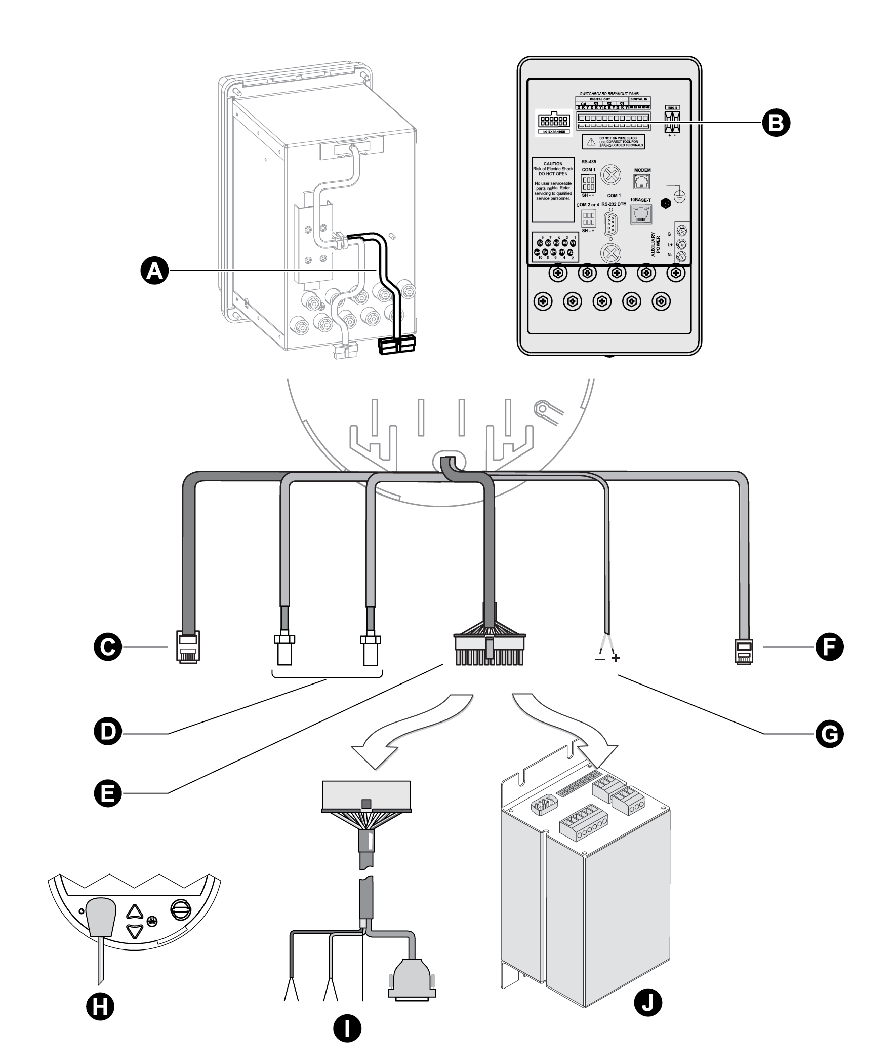
|
A |
Communications wiring on switchboard |
|
B |
Communications wiring on breakout panel |
|
C |
Ethernet 10/100Base-T: RJ45 connector. See Configuring Ethernet connections. |
| D | Cell modem option: SMA connector. Internal modem connections. |
| E | Serial COMs and Expanded I/O: Molex Micro-Fit 24 pin male connector. See Communications options. |
| F | IRIG-B GPS Time Synchronization. |
| G | Modem on COM2: RJ11 male connector. See Internal modem connections. |
| H | ANSI Type II Magnetic Optical Communications Coupler on COM3. This port is located on the front panel. See Configuring the optical port. |
| I | Optical communications breakout cable for serial communications. Ordered separately. See Communications breakout cable. |
| J |
Optional I/O Expander for serial communications (and expanded I/O). Ordered and shipped separately. For more information, see the I/O Expander documentation. Serial COMs: COM1: RS-232 or RS-486 |
Communications options
ION8650 meters have numerous communication possibilities depending on your ordering options and, in the case of the ION8650C, the enabled communications ports.
Not all models have the same communications options available. Contact your Schneider Electric sales representative for the latest ordering options and documentation. You can use all communications ports simultaneously on the ION8650A and ION8650B; you can use the front optical port plus two other ordered communications ports simultaneously on the ION8650C.
Socket and switchboard meters communication options
| Port | Available options | Notes |
|---|---|---|
| COM1 | RS-232 / RS-485 | User selectable RS-232 or RS-485 |
| COM2 | Internal Modem RJ11 | Maximum 57.6 kbps baud rate modem RJ11 connection |
| COM3 | Optical Port | ANSI Type II optical port located at front of meter |
| COM4 | RS-485 | — |
| Cell modem | Internal cell modem | Available on socket meter only |
| Network | Ethernet RJ45 (10/100Base-T) | — |
| IRIG-B | Captured wire connector | Format is unmodulated IRIG-B time code |
Optional switchboard breakout panel communication options
See the ION8650 switchboard installation guide for wiring instructions.
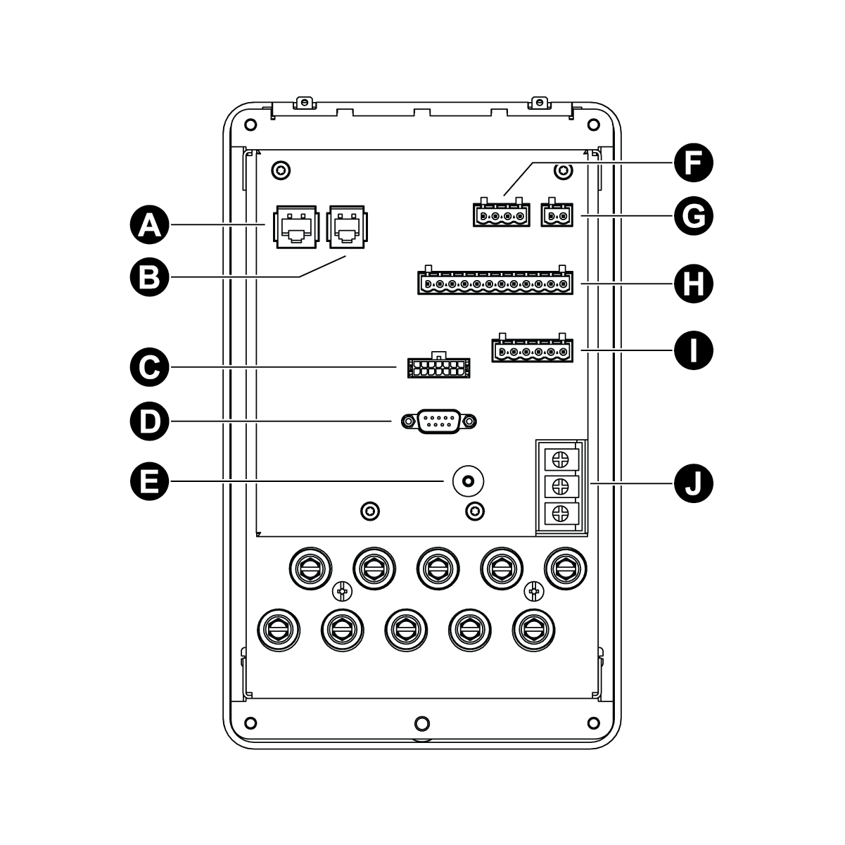
|
Connector type |
|
|
A |
Ethernet (option) |
|
B |
Modem (option) |
|
C |
I/O Expander (option) |
|
D |
COM1 RS-232 |
|
E |
Chassis ground |
|
F |
Digital inputs |
|
G |
IRIG-B |
|
H |
Digital outputs |
|
I |
COM1 RS-485 & COM2 or COM4 RS-485 |
|
J |
Auxiliary power supply (option) |
NOTE: The communications ports on an I/O Expander are not enabled when connected to a breakout panel. Use the RS-485 and RS-232 connectors provided on the breakout panel.
Communications accessories
The following accessories are currently available as separate products:
I/O Expander
The I/O Expander connects with the male Molex connector on the meter to provide I/O capabilities as well as access to standard serial communications ports. Refer to the I/O Expander Installation Guide for details about this device.
Communications breakout cable
The communications breakout cable connects with the male Molex connector on the meter. This is a pre-made cable that provides access to the standard serial communications ports on the meter. Cable length is 5 feet (152 cm).
Molex extension cables
Molex extension cables can be ordered in both 5 and 15 feet (1.5 or 4.5 meter) lengths.
Optical probe
The optical probe attaches to the optical port on the front of the meter and allows on- site communications (for example, with a laptop computer).
ION8650C communications options
The ION8650C supports concurrent communications on the optical port (COM3) and a maximum of two other communications ports for a total of three simultaneous communications connections. If your ION8650C has three communications ports enabled, you must disable one of the active communications ports before you can enable another one in its place. For example, if you have an ION8650C with optional Ethernet enabled, you must disable the Ethernet port in order to communicate over both serial ports (COM1 and COM4).
The default settings vary depending on your order option. See your meter’s Installation guide for details.
NOTE: Switching the active communications ports requires a meter reboot before the changes can take effect.
Enabling and disabling ION8650C communications ports using the front panel
- Press the ALT/ENTER button to enter the SETUP menu.
- Use the arrow buttons to scroll down the menu and select ENABLED COM PORTS, then press ALT/ENTER. Select CONTINUE and press ALT/ENTER when prompted.
- Select the active communications port you want to disable (for example, Ethernet) and press ALT/ENTER. Select DISABLED and press ALT/ENTER. If prompted, enter the meter password to confirm the change.
- Select the communications port you want to enable (for example, COM1) and press ALT/ENTER. Select ENABLED and press ALT/ENTER. Confirm the change if prompted.
- Select REBOOT and press ALT/ENTER. Enter the meter password and confirm the change if prompted. This power cycles the meter and applies the change.
![]() warning
warning
HAZARD OF unintended operation
| ● | Do not use the meter for critical control or protection applications where human or equipment safety relies on the operation of the control circuit. |
| ● | Be aware that an unexpected change of state of the digital outputs may result when the supply power to the meter is interrupted or after a meter firmware or template upgrade. |
Failure to follow these instructions can result in death, serious injury, or equipment damage.
NOTE: Select UNDO & RETURN to exit the ENABLED COM PORTS setup menu without making any changes. Your meter will not reboot.
Enabling and disabling ION8650C communications ports using ION Setup
NOTE: You must manually power cycle the meter to have the changes take effect.
- Select Communications > Enable/Disable and click the Enabled Ports tab.
- Select an available port to enable or disable.
You can only enable or disable communications ports that were ordered with the meter. Ports that were not ordered appear in the list as Not Installed (in the graphic above, COM2 was not ordered).
Click Edit. Enter the meter password, if prompted. The Set Enabled Ports dialog box appears. - Select a check box to enable a listed port or clear a check box to disable a listed port. You can enable a maximum of two of the ports listed in the dialog box.
- Click OK to return to the Setup Assistant. Changes will take effect the next time the meter is power cycled, either manually or in a power outage.
![]() warning
warning
HAZARD OF unintended operation
| ● | Do not use the meter for critical control or protection applications where human or equipment safety relies on the operation of the control circuit. |
| ● | Be aware that an unexpected change of state of the digital outputs may result when the supply power to the meter is interrupted or after a meter firmware or template upgrade. |
Failure to follow these instructions can result in death, serious injury, or equipment damage.