Power quality configuration
Power quality configuration is provided by several modules and frameworks, depending on your meter type, such as the Sag/Swell module, the Transient module, the Mains Signalling Evaluation module, and the IEC 61000-4-30 framework, among others.
See the ION Reference for more information on these modules.
For a description of the scaled operational values (SOV) feature and the alternate scaling registers on the Power Quality page in the Vista component of Power Monitoring Expert, see Scaled operational values.
Configuring power quality settings
Use Power Monitoring Expert or ION Setup to change your meter’s power quality settings.
NOTE: The Sag/Swell module’s Nom Volts setting is used by the Transient module, as well as in other power quality features such as EN50160 and 4-30 calculations. You must set this register to enable these power quality features. If the Sag/Swell module’s Nom Volts setup register is set to zero, these functions are disabled. Nom Volts is typically set when the meter is put into service. If Nom Volts has not been set, enter a value for your system’s nominal voltage (i.e., 120, 277, or 347).
Using the front panel
You cannot configure power quality from the front panel.
Using ION Setup
NOTE: COMTRADE must be DISABLED in order to configure Sag/Swell or Transients.
- Open the Setup Assistant for your meter. See the ION Setup Help for instructions.
- Select the Power Quality > Sag/Swell.
- Select a setting and then click Edit. Configure the settings as required.
NOTE: The Sag/Swell module’s Nom Volts setting is used by the Transient module, as well as in other power quality features such as EN50160 and 4-30 calculations. All power quality functions are disabled if the nominal voltage is set to 0 (zero).
- Click the Transient tab to set the voltage deviation threshold, set the transient waveform recorder depth and frequency, enable COMTRADE waveform records and set other transient settings.
NOTE: The ION8650A features dual waveform capture: Sags are recorded at 32 samples x 54 cycles. Transients waveform capture at 512 samples x 4 cycles.
- Re-enable COMTRADE, if necessary.
Using Designer
Open your meter in Designer and navigate to the Power Quality folder. Right-click a module to edit.
Sag/Swell module settings
The Sag/Swell module monitors voltage waveforms for sags and swells (i.e., ITI [CBEMA] Type 2 and Type 3 disturbances). It then reports each disturbance’s magnitude and duration. The Sag/Swell module can also detect sub-disturbances during a Sag/Swell event. Settings are as follows:
|
Setup register |
Function |
Default |
|
Swell Lim |
This is the magnitude above which a voltage deviation is considered a swell. |
110 |
|
Sag Lim |
This is the magnitude below which a voltage deviation is considered a sag. |
90 |
|
Change Crit |
This is the amount a voltage signal must change during a disturbance to be considered a new sub-disturbance. |
10 |
|
Nom Volts¹ |
This is the nominal power system voltage (used for all power quality functions). Set Nom Volts to 0 (zero) to disable power quality monitoring. |
0 |
|
Hysteresis |
This is the difference in magnitude between the start and end limits for a Sag/Swell. For example, if the sag limit is set to 90% and the hysteresis is set to 2%, the voltage needs to reach 92% before the sag is considered over. |
2 |
|
EvPriority |
The priority assigned to Sag/Swell module events (0 to 255, 255 is highest). |
0 |
¹ The primary power system voltage is sometimes different than the PT Primary setup register value (for example, when the PT Primary is used to indicate winding ratio rather than primary voltage).
You also need to set the EvPriority register value if you want Sag/Swell events to be recorded in the Event Log. To enable Sag/Swell events, the EvPriority value must be greater than the Event Log Controller module’s Cutoff value (the recommended Sag/ Swell EvPriority value is 200). To disable Sag/Swell events so they are not recorded in the Event Log, set EvPriority to 0 (zero).
You can change Swell Lim and Sag Lim, but most applications are served by the default values entered into these registers. The Change Crit setup register does not need to be changed for normal operation.
Transient module settings (ION8650A only)
The Transient module monitors voltage waveforms for transient activity (i.e.
ITI [CBEMA] Type 1 disturbances). The Threshold setup register defines what voltage disturbance magnitude is considered as transient activity. Threshold is interpreted as a percentage of the nominal system voltage, plus 100. For example, if you want transients recorded when voltage deviates from nominal by 20%, enter 120 into the Threshold setup register.
|
Setup register |
Function |
Default |
|
Threshold |
This is the magnitude at which a voltage deviation is considered a transient. |
125 |
|
EvPriority¹ |
The priority assigned Transient module events (0 to 255, 255 is highest). |
0 |
¹ By default, Transient events are not recorded in the Event Log.
You also need to set the EvPriority register value if you want Transient events to be recorded in the Event Log. To enable Transient events, the EvPriority value must be greater than the Event Log Controller module’s Cutoff value (the recommended Transient EvPriority value is 200). To disable Transient events so they are not recorded in the Event Log, set EvPriority to 0 (zero).
Configuring power quality event logging
Use Power Monitoring Expert or ION Setup to change your meter’s power quality event log settings.
NOTE: By default, Power Quality events are not included in the Event Log.
Using the front panel
You cannot configure Power Quality event logging from the front panel.
Using ION Setup
- Open the Setup Assistant for your meter. See the ION Setup Help for instructions.
- Select Logging > Event Log.
- On the Event tab, select SS1 EvPriority (Sag/Swell Event Priority) or TR1 EvProiority (Transient Event Priority), and then click Edit.
– To stop Sag/Swell or Transient events from being recorded in the Event Log, set event priority to zero (0).
– To include Sag/Swell or Transient events in the Event Log, the event priority must be greater than the Event Log Cutoff (EL1 Cutoff) value. The recommended EvPriority value for enabling event logging is 200.
Using Designer
Open your meter in Designer and navigate to the Power Quality Setup Framework. Right-click the Sag/Swell or Transient module to edit.
Power quality standards compliance
The ION8650 has additional frameworks and settings related to the power quality standards below.
EN50160 settings (ION8650A and ION8650B)
The EN50160 framework is composed of numerous ION modules including: Mains Signaling Evaluation, Harmonics Evaluation, Voltage Harmonics, Flicker, and more.
NOTE: To avoid missing data in your EN50160 reports, use a meter with an auxiliary power option connected to a UPS (Uninterruptible Power Supply) so that the EN50160 framework continues to operate during power outage situations.
See EN50160 compliance logging (ION8650A and ION8650B only) for information on EN50160 parameter logging.
See the Power Quality: ION Meters and EN50160 technical note for details.
4-30 settings (ION8650A and ION8650B only)
IEC 61000-4-30 power quality standard compliance is provided by a variety of ION modules including: Power Quality Aggregator, Harmonics Measurement, Disturbance Analyzer, Symmetrical Components, Mains Signaling Evaluation, Sag/Swell and more.
See the IEC 61000-4-30 Compliance and ION Meters technical note for details.
COMTRADE settings (ION8650A only)
The meter can provide waveforms in COMmon format for TRAnsient Data Exchange (COMTRADE) format. COMTRADE records are created from the existing Waveform Recorder modules, which are connected to the COMTRADE module.
See the COMTRADE and ION Technology technical note for details.
Disturbance Direction Detection
Your meter has disturbance direction detection capabilities to help you determine the location of a power system disturbance. When a disturbance occurs, the meter analyzes the disturbance information to determine the direction of the disturbance relative to the meter. This analysis includes a confidence level indicating the level of certainty that the disturbance is in the determined direction and is stored in your meter’s event log.
Disturbance direction detection can help locate the source of a disturbance when used in a system of disturbance direction detection devices, as shown in the following diagram.
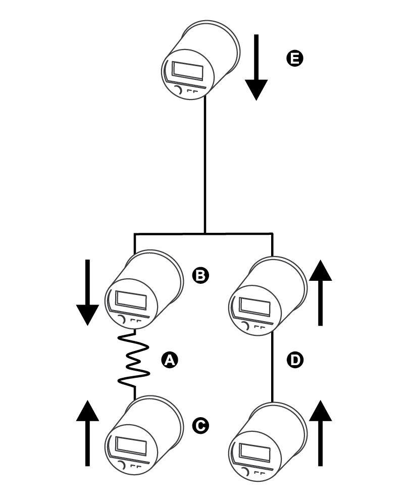
|
A |
Disturbance location |
|
B |
Meter #1 reports downstream disturbance |
|
C |
Meter #2 reports upstream disturbance |
|
D |
Meters report upstream disturbance |
|
E |
Meter reports downstream disturbance |
The arrows show the direction the meters have determined for the disturbance. With this information, you can focus on the section between meter #1 and meter #2 to find the cause of the disturbance.
NOTE: The disturbance direction detection feature is only available on the ION8650A and ION8650B meter models.
Viewing disturbance direction detection events
The results of the disturbance direction detection algorithm appear in the meter’s event log. The image below shows an example of how the Disturbance Direction Detection event appears in your meter’s event log when viewed using ION Setup.
NOTE: You can view your meter’s event log through the display, ION Setup or using the meter’s webpages.
Related topics:
- See the ION Reference for more detailed information about the Disturbance Direction Detection module.
- See Event logging for more information about your meter’s event log.