Digital inputs
Digital inputs are often used to monitor the status of switches or contacts. For example, status contacts on circuit breakers.
You can also use digital inputs for pulse counting or input metering applications, such as:
- WAGES (water, air, gas, electricity, steam) monitoring
- Conditional energy applications
- IRIG-B time synchronization
There are three main components of the digital input sequence:
- Digital input signal: the received signal.
- State output: the device's digital input state after detecting the digital input signal.
- Trigger output: outgoing pulses based on state output transitions, you can change the trigger output behavior by changing the Input Mode.
You can configure digital inputs to respond differently to changes in the digital input signal and signal types.
Pulse mode
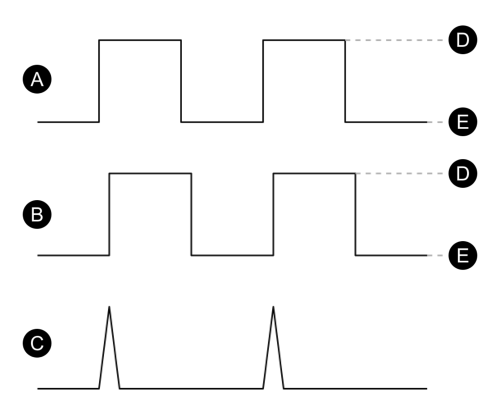
When the Input Mode of a digital input is set to PULSE, the device generates a pulse at the trigger output when the state output changes from off to on. No pulse is generated when the state output changes from on to off.

| A | Digital input signal |
| B | State output |
| C | Trigger output (Input Mode set to Pulse) |
| D | On |
| E | Off |
KYZ mode
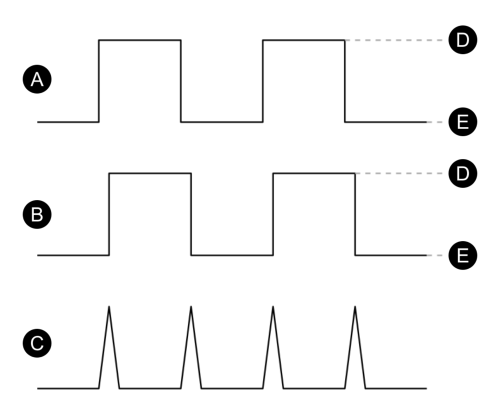
When the Input Mode of a digital input is set to KYZ, the device generates a pulse at the trigger output for each state output change. For example, transitions from off to on and from on to off.

| A | Digital input signal |
| B | State output |
| C | Trigger output (Input Mode set to KYZ) |
| D | On |
| E | Off |
A/C mode
When the Input Mode of a digital input is set to A/C, that digital input detects low voltage AC signals.
Note: The frequency detection range varies by device; see your device’s documentation for specifications.
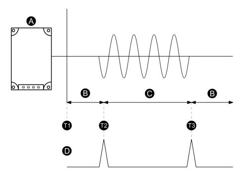
For example, this mode could be used to monitor a low voltage AC fan controller. When the device detects an AC signal (T2), the state output changes to on and a pulse is generated from the trigger output. When the device detects that the signal from the fan controller has stopped (T3), the state output changes to off and another pulse is generated from the trigger output.

| A | Fan controller |
| B | State output is off |
| C | State output is on |
| D | Trigger output (Input Mode set to A/C) |
| T1 | No signal from the fan controller. |
| T2 | The device detects a signal from the fan controller, the trigger output sends a pulse. |
| T3 | The device detects that the signal from the fan controller has stopped, the trigger output sends a pulse. |
IRIG-B time synchronization
You can use a digital input to synchronize the device clock to an IRIG-B time source.
Configure a digital input and the device clock to use IRIG-B time synchronization.