Configure the Properties on the Mapping Tab
The Forms of SCADAPack x70 <Point Type> Configuration items include a Mapping tab. By default, the settings on this tab are disabled (the Mapping property is set to 'No Mapping').
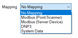
You only need to set the 'Mapping' property to another option if one of the following applies:
Either:
- The SCADAPack x70 device with which the SCADAPack x70 Configuration item is associated requests data from a Server/Remote device
and:
- The SCADAPack x70 Configuration item that you are configuring represents an input or output on that Server/Remote device.
If both of the above apply, use the Mapping property to specify the communications protocol that the SCADAPack x70 device is to use to communicate with the Server/Remote device. Other properties will become available on the Mapping tab; use the properties to specify the required settings to enable the SCADAPack x70 device to retrieve the data from the Server/Remote device.
If you want to use the data from the Server/Remote device in Geo SCADA Expert, in addition to configuring the relevant settings on the Mapping tab, you have to associate the SCADAPack x70 Configuration item with a SCADAPack x70 protocol-specific Point. You use the Point to specify how Geo SCADA Expert processes the data that it retrieves from the Server/Remote device for that particular input or output (see Points and Configuration Items Supported by the Driver).
Or:
- The SCADAPack x70 <Point Type> Configuration item is being used to monitor or control system data on a SCADAPack x70 device.
In which case, use the Mapping property to specify the item of system data with which the SCADAPack x70 Configuration item is associated.
If you want to use the SCADAPack x70 device's system data in Geo SCADA Expert, in addition to configuring the relevant settings on the Mapping tab, you need to associate the SCADAPack x70 Configuration item with a SCADAPack x70 protocol-specific Point. You use the Point to specify how Geo SCADA Expert processes the system data that it retrieves from the SCADAPack x70 device for that particular input or output (see Points and Configuration Items Supported by the Driver).
You only have to set the Mapping property to Modbus (Point Scanner) or Modbus (Server Device) if either of the following apply:
- The SCADAPack x70 device with which this Analog, Digital, or Counter Configuration item is associated is operating as a Modbus RTU Client. Additionally, the input or output that this Analog, Digital, or Counter Configuration item represents is on a Modbus Server Device from which the SCADAPack x70 device requests data.
- The SCADAPack x70 device with which this Analog, Digital, or Counter Configuration item is associated is operating as a Modbus IP Clients. Additionally, the input or output that this Analog, Digital, or Counter Configuration item represents is on a Modbus /TCP Server from which the SCADAPack x70 device requests data.
With either of the above scenarios, you have to set the Mapping property to either of the following options, whereupon the corresponding properties are displayed. You have to choose the corresponding Mapping based on whether you have chosen automatic or manual creation of Modbus Point Scanners(see Configure Modbus Point Scanners Settings). Configure the properties as required:
- Modbus (Point Scanner)—Use this option to link the SCADAPack x70 Configuration Item to a Modbus Point Scanner.
You use this mapping in conjunction with Modbus Server devices where the Create Automatically option is disabled (see Configure Modbus Point Scanners Settings).
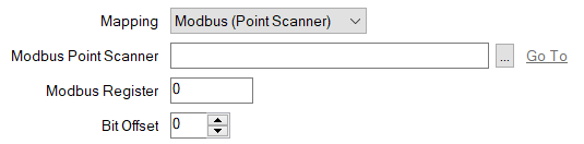
- Modbus Point Scanner—Specify the SCADAPack x70 Modbus Point Scanner item that is being used to map to the point on the Modbus RTU Server or Modbus/TCP Server. Use the browse button to display a Reference browse window and then select the required entry from the window.
- Modbus Register—Specify the Modbus Register address at which the point is located in the Modbus RTU Server or Modbus/TCP Server. The address has to be within the range that is available to the SCADAPack x70 Modbus Point Scanner item specified in the field above.
- Bit Offset—This field is enabled only if the SCADAPack x70 Digital Configuration item is associated with a Modbus Point Scanner that has its Modbus Data Type field set to UINT (Digital). Use the spin box to specify the bit of the Modbus RTU Server or Modbus/TCP Server register to which the object is mapped. You can set the bit value between 1 and 16 inclusive. The default value is 1 and it is the least significant bit in the Modbus register, while 16 is the most significant bit in the Modbus register.
- Modbus (Server Device)—Use this option to link the SCADAPack x70 Configuration Item to a Modbus Server Device.
You use this mapping in conjunction with Modbus server devices where the Create Automatically option is enabled. For two or more SCADAPack x70 objects (analogs/digitals/counters) to share the same automatically created Modbus Point Scanner, they must have the same settings and be mapped to adjacent registers (within the Maximum Gap Size) (see Configure Modbus Point Scanners Settings).
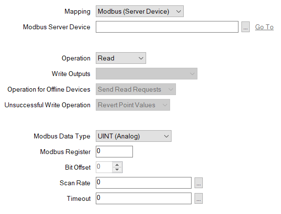
- Modbus Server Device—Specify the SCADAPack x70 Modbus Server Device item that is being used to map to the point on the Modbus RTU Server or Modbus/TCP Server. Use the browse button to display a Reference browse window and then select the required entry from the window.
- Operation—Use this combo box to specify whether the SCADAPack x70 reads from, or writes to, the point on the Modbus Server device. Select from Read (the default setting), Write, or Read/Write. The options that are available vary, depending on the Modbus Data Type. The Write option is not available for counter objects.
When the Operation field is set to Read, the Write Outputs, Operation for Offline Devices, and Unsuccessful Write Operation fields are disabled.
If writing to DINT, Real or UDINT data types, the Write Holding Registers setting must be set to Multiple (Function Code 16). The options define the type of data to which the Scanner can write (see Configure the Modbus Point Scanner Configuration).
- Write Outputs—Define when a write command is issued. This combo box is only available for use when the Operation field is set to Write or Read/Write. Choose from the following:
- At Scan Rate—Write to the point at the Default Scan Rate configured for Server device (see Configure a Modbus Server Device) or at the Scan Rate defined on this form (see Scan Rate below). This option is enabled only when the Operation field is set to Write. This is the default setting when the Operation field is set to Write.
- On Change—Write to the point when the point value changes. This option is available when the Operation field is set to Write or Read/Write. This is the default setting when the Operation field is set to Read/Write.
- At Scan Rate and On Change—Write to the point at both the Scan Rate configured for the server device, and when the point value changes (see Configuring a Modbus Server Device). This option is enabled only when the Operation field is set to Write.
- Operation for Offline Devices—This combo box is only available when the Operation field is set to Read/Write. Use this combo box to specify the operation that the SCADAPack x70 should perform while the point is offline. Choose from the following:
- Send Read Requests—Send read requests to the server at the scan rate specified for the device, or at the Scan Rate specified in the field below if that scan rate differs from the device scan rate. This is the default setting.
- Send Write Requests—Send write requests to the server after a change in value or after a write command from another source.
If a write request is sent while a read request is still in progress, the value of the SCADAPack x70 objects that are part of both requests is not updated.
If a write request is sent while there are buffered read requests for that point scanner, the buffered read requests are canceled. If a read request is in progress, it continues.
- Unsuccessful Write Operation—This combo box is only available when the Operation field is set to Read/Write. Use this combo box to specify the operation that the SCADAPack x70 should perform when a write failure occurs. Choose from the following:
- Revert Point Values—Return the SCADAPack x70 objects to their previous value when the write operation is unsuccessful. This is the default setting.
- Retain Point Values—Keep the current values of the SCADAPack x70 objects when the write operation is unsuccessful.
- Modbus Data Type—Use this combo box to specify the format of the point value. The Modbus Data Type options comprise a combination of the following:
- Discrete (Digital)—The value is formatted as a discrete number (digital points only).
- UINT (Digital)—The value is formatted as unsigned 16-bit data. Each UINT comprises 1 Modbus register (digital points only).This is the default option for digital points.
- UINT (Analog)—The value is formatted as unsigned 16-bit data. Each UINT comprises 1 Modbus register (analog points only). This is the default option for analog points.
- INT—The value is formatted as signed 16-bit data. Each INT comprises 1 Modbus register (analog points only).
- DINT—The value is formatted as signed 32-bit data. Each DINT comprises 2 Modbus registers (analog points only).
When the Operation field is set to 'Write' or 'Read/Write', this option is only available if the associated Modbus Server Device's Write Holding Registers property is set to 'Multiple (Function Code 16)'. For information about configuring the latter property, see Configure Modbus Server Device Configuration Settings.
- Real (Floating Point)—The value is formatted as an IEEE 32-bit single-precision floating point value. Each REAL comprises 2 Modbus registers (analog points only).
When the Operation field is set to 'Write' or 'Read/Write', this option is only available if the associated Modbus Server Device's Write Holding Registers property is set to 'Multiple (Function Code 16)'. For information about configuring the latter property, see Configure Modbus Server Device Configuration Settings.
- UINT (Counter)—The value is formatted as unsigned 16-bit data. Each UINT comprises 1 Modbus register (counter points only). This is the default option for counter points.
- UDINT—The value is formatted as unsigned 32-bit data. Each UDINT comprises 2 Modbus registers (counter points only).
When the Operation field is set to 'Write' or 'Read/Write', this option is only available if the associated Modbus Server Device's Write Holding Registers property is set to 'Multiple (Function Code 16)'. For information about configuring the latter property, see Configure Modbus Server Device Configuration Settings.
- Modbus Register—Specify the Modbus Register address at which the point is located in the Modbus RTU Server or Modbus/TCP Server. The valid range depends on the Modbus data type.
- Discrete (digital):
- 5-digit register address—1 to 9999 (Read, Write) or 10001 to 19999 (Read)
- 6-digit register address—1 to 65535 (Read, Write) or 100001 to 165535 (Read)
- INT, UINT, DINT, UDINT and Real (Floating Point):
- 5-digit register address—30001 to 39999 (Read) or 40001 to 49999 (Read, Write)
- 6-digit register address—300001 to 365535 (Read) or 400001 to 465535 (Read, Write)
- Discrete (digital):
- Bit Offset—This field is enabled only if the Modbus Data Type field is set to UINT (Digital). Use the spin box to specify the bit of the Modbus RTU Server or Modbus/TCP Server register to which the object is mapped. You can set the bit value between 1 and 16 inclusive. The default value is 1 and it is the least significant bit in the Modbus register, while 16 is the most significant bit in the Modbus register.
- Scan Rate—Define the rate, in milliseconds, at which the point scanner will send requests. Enter the required interval in the OPC Time Format. You can enter the value directly in the field, or use the Interval window (accessed via the field's browse button) to specify the required value. The default setting is 0.
To use the same scan rate as the Modbus Server (see Configure Modbus Server Device Configuration Settings), leave the default setting of 0.
- Timeout—Specify the amount of time that the SCADAPack x70 device should wait for a response when it scans the point on the Modbus Server device. To use the same timeout as the Modbus Server, leave the default setting of 0.
If the SCADAPack x70 device does not get a response within this time, it will try the scan again until it exceeds the Maximum Consecutive Timeouts count. If the SCADAPack x70 device still cannot get a response after the retries, it will determine that it cannot communicate with the device (see Configure Modbus Server Device Configuration Settings).
Enter the required interval in the OPC Time Format. You can enter the value directly in the field, or use the Interval window (accessed via the field's browse button) to specify the required value.
The timeout value that you enter is for each scan.
You only have to set the Mapping property to ‘DNP3’ if the following applies:
- The SCADAPack x70 device with which this Analog, Digital, or Counter Configuration item is associated is operating as a DNP3 Controlling Station. Additionally, the input or output that the Analog, Digital, or Counter Configuration item represents is on a DNP3 Outstation from which the SCADAPack x70 device requests events. (A DNP3 Outstation can be another SCADAPack x70 device, or a different type of device, such as a remote terminal unit (RTU), a programmable logic controller (PLC), or a smart device with DNP3 protocol capability.)
With the above scenario, you need to set the Mapping property to ‘DNP3’, whereupon the following properties are displayed. Configure the properties as required:
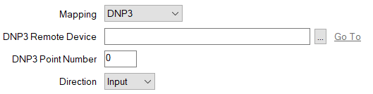
- DNP3 Remote Device—Specify the SCADAPack x70 DNP3 Remote Device item that is being used to map to the point on the DNP3 Outstation. Use the browse button to display a Reference browse window and then select the required entry from the window.
- DNP3 Point Number—Specify the DNP3 Point Number that is assigned to the point on the DNP3 Outstation.
- Direction—Use the combo box to specify whether the point on the Remote device is an Input or Output. With a Counter Configuration item, the direction is set to 'Input'.
You only have to set the Mapping property to 'System Data' on a SCADAPack x70 <Point Type> Configuration item that is being used to monitor or control system data on a SCADAPack x70 device. When you do so, the following properties are displayed:
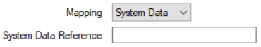
- System Data Reference—Enter the name of the item of system data that this particular <Point Type> Configuration item is to reference in the SCADAPack x70 device. The entry should match the name of the item of system data exactly. Refer to the documentation provided with the SCADAPack x70 device for information about the items of system data that are supported by the device.
The entry must begin with the
SYS_prefix and can be a maximum of 32 characters long. It can contain a mixture of alphanumeric and underscore characters, but cannot contain any spaces.There is no automatic checking mechanism to confirm whether the entry in the System Data Reference field does match the name of an item of system data in the SCADAPack x70 device. As such, care should be taken to manually check that the string entered in the field is correct.
Further Information
Specify the role of a SCADAPack x70 device in a SCADA network: see Configure the Device Options.
Configure Geo SCADA Expert to Communicate with Downstream Server/Remote Devices.
Use system data to trigger Daylight Saving Time (DST) adjustments: see Configure the Time Zone Settings for Local Operations.