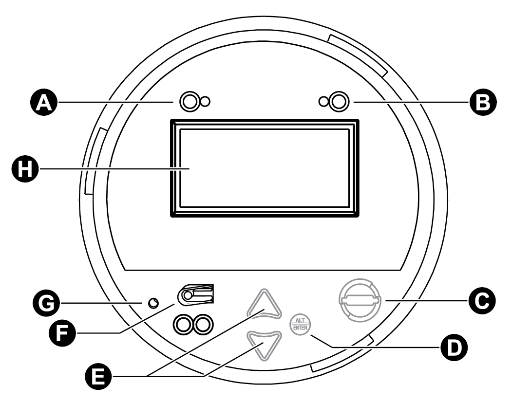
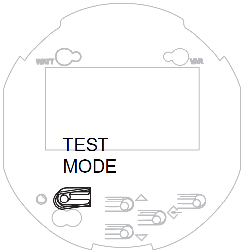
Front panel features
The front panel includes a liquid crystal display (LCD) with detailed graphics and text, up and down arrow buttons for screen navigation and basic setup procedures, as well as LED pulsers for testing the meter. This section outlines the features available on the front panel of the meter.
|
A |
Watt pulser: A set of LEDs (infrared, red) used for real energy pulsing. |
|
B |
VAR pulser: A set of LEDs (infrared, red) used for reactive energy pulsing. |
|
C |
Demand reset switch: Resets the peak demand values in the meter. Can be activated with the cover on or off. |
|
D |
Round button (Alt/Enter): Press to select a highlighted option. Also used to toggle between Norm and Alt display modes. Press and hold for 3 seconds to access Setup menu. |
|
E |
Navigation buttons: Press the up or down buttons to scroll and highlight a different menu item or to increase/decrease the value of a highlighted number. Press and hold the up button for 3 seconds to move the cursor to the left. Press and hold the down button for 3 seconds to move the cursor to the right. |
|
F |
Test mode button: Located under the front label, this places the meter into Test mode, ceasing accumulation of billable quantities. |
|
G |
Master reset button: Located in a recessed pinhole under the front label to prevent accidental activation. You must remove the meter cover and its label to access it. |
|
H |
Meter LCD screen |
LED pulsers
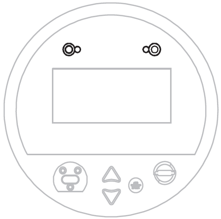
Two LED pulsers located near the top of the front panel represent WATT (to the left) and VAR (to the right).
These LEDs are preconfigured for energy pulsing. The adjacent infrared outputs are connected to the LEDs and pulse at the same rate. Pulse rates can be adjusted by editing the settings of the Calibration Pulser module; for a detailed description of LED pulser operation, see Energy pulsing with LEDs.
Demand reset switch
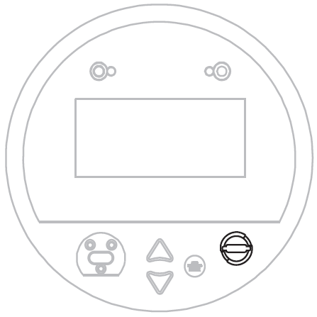
Located on the front of the meter's external cover assembly, the demand reset switch resets the peak demand values logged in the meter. This switch can be activated with the cover on or off. When the meter is in TEST mode, the demand reset switch resets the test demand parameters.
In most applications, the demand reset switch is sealed with an anti-tamper mechanism; a through-hole in the switch can accommodate either an external seal or a locking mechanism. See for more information on anti-tamper sealing.
A Demand Lockout Time register sets the minimum time allowed between consecutive demand resets; the meter ignores any attempts to reset the demand outside the bounds of the register. The default value for the Demand Lockout Time is 25 days (2160000s). For details on the Demand Lockout Time setup register, see Configuring demand reset lockout time.
Navigation buttons

The navigation buttons are the up and down arrow buttons and the round ALT/ENTER button. Press the up or down arrow buttons to manually scroll back or forth through the available displays and temporarily halt the display screen’s automatic scrolling function. Press ALT/ENTER to toggle between NORM and ALT display modes. The automatic scrolling function restarts 60 seconds after a button was last pressed.
Hold the ALT/ENTER button for approximately three seconds to display the setup menu. You can then use the navigation buttons to view the device's configuration or edit basic settings. See Setup menus for further instruction on modifying the device's configuration using the front panel buttons.
Optical port

An optical port facilitates infrared communication with the device. For details on how to configure and use this port, see Configuring the optical port.
Master reset button
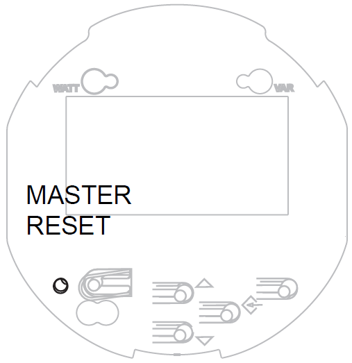
You must remove the meter’s cover as well as the front panel label to access the master reset button; it is located in the lower left of the faceplate. This button is recessed to prevent accidental activation. For instructions on removing the meter cover and performing a master reset, and information on what parameters are reset, see Performing a master reset from the front panel.
Use the master reset button to delete most accumulated values and all derived revenue measurements from the meter.
TEST mode button
The TEST mode button is located under the meter's external cover assembly; it places the meter into TEST mode. While in TEST mode, the meter stops accumulating billable quantities; energy and demand measurements are accumulated in TEST mode registers.
See TEST mode for more details on this mode of operation.