Configuring the meter with the front panel
Using the meter’s front panel, you can navigate through different menus to perform basic setup on your meter.
NOTE: If you have a hardware-locked meter, only the basic communications parameters can be changed in NORM mode. You must enter TEST mode to change other meter parameters on the hardware-locked meter. See for more details.
Accessing the SETUP menu
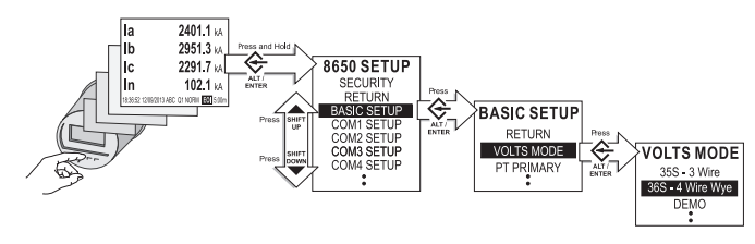
To access the SETUP menu, press and hold the front panel's ALT/ENTER button while the meter is displaying power system data. Within the SETUP menu is a list of sub- menus that contain the meter’s configurable settings. The menu items are described in Front panel features.
Press the up or down arrow buttons to navigate through the menu. Highlight a menu item and press the ALT/ENTER button. When you select an item from the SETUP menu, you are presented with another menu of the settings in the meter. You may need to navigate several layers of menus to access the setting you want to change.
The following diagram shows how the buttons are used to navigate the menus:
The settings contained in the SETUP menu are:
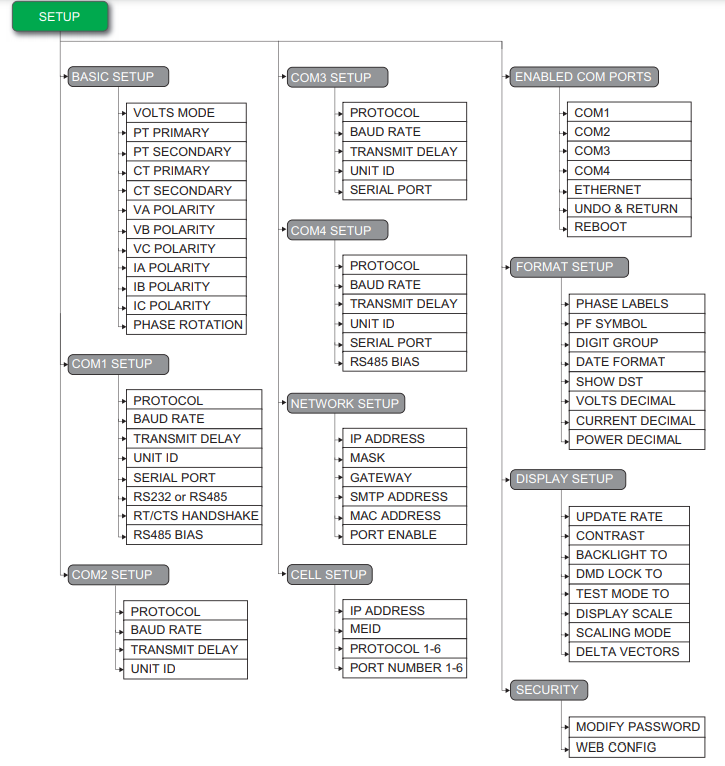
Each of the main setup screens and the settings you can configure are discussed in Setup menus.
NOTE: Your display may appear differently than shown, depending on your meter’s model and configuration.
NOTE: The ENABLED COM PORTS setup menu only appears on the ION8650C.
Navigating the front panel screens
Use the up and down arrow buttons to scroll through the menu items. When the setting you want to change is highlighted, press the ALT/ENTER button.
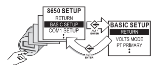
To return to a previous screen, use the up or down arrow button to highlight the RETURN menu item and then press the ALT/ENTER button.
Configuring parameters using the navigation buttons
Use the up or down arrow buttons to change the value (if numeric) or the setting (if enumerated) of the highlighted parameter.
To change the position of the cursor, press the up or down arrow buttons for about one second. The up arrow button moves the cursor one position to the left and the down arrow button moves the cursor one position to the right. Once you have the value you want, press the ALT/ENTER button to select it.
NOTE: When setting Ethernet values (IP address, default gateway, etc.), press the up arrow button to insert additional digit spaces. Press the down arrow to remove digit spaces (see NETWORK SETUP menu for more information).
OUT OF RANGE screen
When editing numeric data, the numbers displayed on the screen below MIN and MAX indicate valid entry bounds. If you enter a value outside valid bounds, you are presented with a message stating that the value is out of range. You can then either return to the register you were editing or choose to exit.
Entering the front panel password with basic security enabled
With basic security enabled on the meter, you are presented with the password screen when you attempt to change a setting on the front panel. After you enter the correct password, you do not have to re-enter it for other any other changes unless you exit the configuration session, or the session has elapsed.
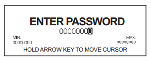
To enter the password:
- Use the arrow buttons to change the value of the highlighted digit. The up arrow increments the number and the down arrow decrements it.
- Hold down an arrow button for about one second to change the position of the cursor. The up arrow moves the cursor left one position and the down arrow moves the cursor right one position.
-
Press the ALT/ENTER button once you have the value that you want.

Advanced security username and password
If advanced security has been enabled on your meter, you are required to provide your username and password when changing the meter’s settings through the front panel. See Managing user accounts for more information
Confirming configuration changes
The CONFIRM CHANGE screen appears when you attempt to change the meter’s settings through the front panel. This allows you to cancel an unwanted configuration change. The front panel also informs you when an entry is out of range. Select YES to confirm your change or NO to cancel it, then press the ALT/ENTER button to return to the previous setup screen.
Setup menus
The following sections describe the setup menus in more detail.
BASIC SETUP menu
The BASIC SETUP menu lets you set volts mode, potential transformer (PT) and current transformer (CT) ratios and various other settings (such as voltage and current polarities) so that you can ensure that your meter is adequately set for your application.
To access the BASIC SETUP menu with the meter’s front panel:
- Press and hold the ALT/ENTER button on the front panel of the meter. After about three seconds the SETUP screen appears.
- Use the up or down arrow buttons to navigate to the BASIC SETUP menu. Press the ALT/ENTER button.
- Press the up or down arrow buttons to navigate to the appropriate parameter, then press the ALT/ENTER button to edit the parameter.
Many of these settings are configured when the meter is initially put into service (the device will not operate properly until Volts mode and PT and CT ratios are set), but some settings may need to be changed to refine the device’s operation.
NOTE: If you have a hardware-lockable meter, you must put the device into TEST mode prior to making changes to the BASIC SETUP parameters. For TEST mode information, see TEST mode.
The BASIC SETUP menu has the following settings:
| Menu item | Setting options | Default | Description |
|---|---|---|---|
| Volts mode1 |
|
*See note |
The power system’s configuration and supported form factor. 36S - 4 Wire Wye is only available on the socket meter.
Note: The default setting varies depending on the meter form factor. Ensure you verify that the correct option is selected for your power system before putting the meter into service. |
| PT Primary1 | 1.0 to 999999.00 | 120 | The Potential Transformer’s primary winding rating |
| PT Secondary1 | 1.0 to 999999.00 | 120 | The Potential Transformer’s secondary winding rating |
| CT Primary1 | 1.0 to 999999.00 | 5 | The Current Transformer’s primary winding rating |
| CT Secondary1 | 1.0 to 999999.00 | 5 | The Current Transformer’s secondary winding rating |
| VA Polarity |
|
NORMAL | The polarity of the Potential Transformer on V1 |
| VB Polarity |
|
NORMAL | The polarity of the Potential Transformer on V2 |
| VC Polarity |
|
NORMAL | The polarity of the Potential Transformer on V3 |
| IA Polarity |
|
NORMAL | The polarity of the Current Transformer on I1 |
| IB Polarity |
|
NORMAL | The polarity of the Current Transformer on I2 |
| IC Polarity |
|
NORMAL | The polarity of the Current Transformer on I3 |
| Phase Rotation |
|
ABC | The expected rotation of the voltage phases (ABC or ACB) |
1These registers are typically set when the device is commissioned. Changing the values of these registers while the device is in service is not recommended.
COM port setup menus
See Communications overview more information on configuring meter communications.
To make changes to communications settings with the meter’s front panel, hold down the ALT/ENTER button for three seconds to enter the SETUP menu, then press the down arrow button to select the COM SETUP you want.
Depending on the communications options ordered with your meter, the following menu items are available:
| Menu item | Description |
|---|---|
|
COM1 Setup |
Settings for the selectable RS-232 or RS-485 communications port. |
|
COM2 Setup |
Settings for the internal modem port. |
|
COM3 Setup |
Settings for the optical communications port located on the meter’s front panel. |
|
COM4 Setup |
Settings for the COM4 RS-485 port. |
|
Network Setup |
Settings for the Ethernet communications port. |
|
Cell Setup |
Settings for the cellular modem port. |
|
Enabled COM Ports |
Set which two COM ports are enabled for communication, in addition to COM3 (front optical port) which is always enabled. This menu is only available on the ION8650C. |
NOTE: For hardware-locked meters, you must be in TEST mode to alter these COM port settings.
Serial COM port settings
There are three main parameters that you must set or verify if your meter is connected to a serial network (including modem communications): Unit ID, Baud Rate, and Protocol.
NOTE: Other parameters such as TRANSMIT DELAY are used in advanced configuration or fine-tuning your system. The main parameters are the most common parameters required to get your meter communicating.
To configure the COM port settings:
-
Press and hold the ALT/ENTER button on the front panel of the meter. After about three seconds the SETUP screen appears.
-
Use the up or down arrow buttons to navigate to the COM port that you want to configure. Press the ALT/ENTER button.
-
Press the up or down arrow buttons to navigate to parameter you want to edit then press ALT/ENTER.
- Use the up and down arrow buttons to change the value of the parameter then press ALT/ENTER.
The menu items, and their setting options and default configurations, are listed in the following table for COM1 (selectable RS-232 or RS-485), COM2 (modem), COM3 (optical port) and COM4 (RS-485).
| Applies to... | Menu item | Setting options | Default | Description |
|---|---|---|---|---|
|
All |
Protocol |
All COM ports: None1, ION, Modbus RTU, DNP V3.00, DLMS, GPS:TrueTime/Datum2, GPS Arbiter2, GPS Arbiter-Vorne2, Factory Additional protocols on COM1 and COM4: Modbus Master3, EtherGate4, ModemGate3 |
ION |
Specifies the protocol used by the communications port. |
|
All |
Baud Rate |
300, 1200, 2400, 4800, 9600, 19200, 38400, 57600, and 115200 bps |
9600 bps |
Specifies the baud rate of the serial port. Ensure all devices on the same loop are configured to use the same baud rate. |
|
All |
Transmit Delay |
0.0 to 1.0 s. |
0.01s (10ms) |
The amount of time in seconds that the meter waits for communications acknowledgments. |
|
All |
Unit ID |
1 to 9999 |
COM1: Unit ID is based on the serial number5. COM2: 101 COM3: 102 COM4: 103 |
Sets the meter Unit ID. A unique Unit ID is required for each device (including all the devices on a ModemGate or EtherGate serial loop). |
|
COM1 |
RS232 OR RS485 |
RS232 or RS485 |
RS485 |
Specifies the communications mode used by COM1. |
|
COM1 (RS-232 only) |
RTS/CTS Handshake |
RTS/CTS or RTS with Delay |
RTS with Delay |
Specifies the flow control used by the communications port. |
|
COM1 (RS-485 only) and COM4 |
RS485 Bias |
OFF or ON |
OFF |
Enables or disables RS485 biasing. See RS-485 biasing for more information. |
|
COM1, COM3 and COM4 |
Serial Port |
8O1, 8O2, 8N1, 8N2, 8E1, 8E2 |
8N1 |
Sets the parity and data format. For example, 8N1 is eight (8) data bits, no (N) parity bit and one (1) stop bit. Ensure that all devices on the same loop are set to the same format. |
1Select None from the Protocol setting options to disable the COM port.
2SeeTime synchronization for more details about GPS settings. See also the Time Synchronization & Timekeeping technical note for further details on using the meter’s time synchronization functions.
3Modbus Master is not available on the ION8650C.
4See Configuring Ethernet connections and Internal modem connections for more details.
5Unit ID for COM1 is based on the meter’s serial number. For example, if the serial number is PA-0009B263-01, the Unit ID is set in the factory to 9263.
NETWORK SETUP menu
There are two main parameters that you must set or verify if your meter is connected to an Ethernet network: IP address and subnet mask address.
NOTE: There are other parameters, such as GATEWAY ADDRESS and SMTP ADDRESS, that are used in advanced configuration or in fine tuning your system. The main parameters are the most common parameters required to get your meter communicating.
The menu items, and their setting options and default configurations, are as follows:
| Menu item | Setting options | Default | Description |
|---|---|---|---|
|
IP Address |
0.0.0.0 to 255.255.255.255 |
None |
Sets the IP address for the meter. |
|
Mask |
0.0.0.0 to 255.255.255.255 |
None |
Used if subnet masking applies to your network – see your network administrator to determine if subnet mask is used. |
|
Gateway |
0.0.0.0 to 255.255.255.255 |
None |
Used in multiple network configurations – see your network administrator to determine if gateway is used. |
|
SMTP Address |
0.0.0.0 to 255.255.255.255 |
None |
Sets the IP address for the SMTP mail server that is configured to forward mail from the meter to the final destination – see your network administrator to determine if the SMTP mail server is used. |
|
MAC Address |
Read-only factory-set hexadecimal value |
The MAC address is read-only and provided for information purposes only. |
|
|
Port Enable |
|
Yes |
Specifies whether the network ports are enabled or disabled. |
Most network settings can be configured through the front panel; all network settings can be modified in Power Monitoring Expert or ION Setup. See Configuring Ethernet connections for more information.
NOTE: Configuring the IP Address, Mask, Gateway, and Port Enable settings incorrectly can cause network disruptions. See your Network Administrator for more information.
notice
data Loss
Maintain sufficient access to communicate to and configure your device.
Failure to follow these instructions can result in data loss.
Typically, your network administrator provides you with the appropriate IP address for the meter. The subnet mask and gateway settings are only required if you have communications between multiple Ethernet networks and if subnetting is implemented.
Use the navigation buttons to edit the values of the network settings so that they match your system addresses. As you configure the network addresses, the front panel automatically discards unnecessary leading zeros from each three-digit grouping. The hidden leading zeros appear (and disappear again) as you move the position of cursor across the network address.
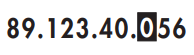
In the example above, the highlighted zero is discarded as soon as you change the position of the cursor.
CELL SETUP menu
The CELL SETUP menu contains the following values that configure the cellular modem:
| Menu item | Setting options | Default | Description |
|---|---|---|---|
|
IP Address |
0.0.0.0 to 255.255.255.255 |
Not configurable |
Displays the IP address assigned to the cell modem by the network |
|
MEID/CCID |
Not configurable |
Not configurable |
Displays Mobile Equipment Identifier |
|
Protocol 1-6 |
None, ION, Modbus TCP, DNP 3.0 |
None |
Specifies the protocol used for connection 1–6 |
|
Port Number 1-6 |
1 - 65535 |
0 |
Specifies the port number to establish connection 1–6 |
|
IP Address |
|
Yes |
|
NOTE: To disable the connection to a port, set the Protocol to None. This allows you to restrict the number of simultaneous connections to the meter through the cell modem.
ENABLED COM PORTS menu (ION8650C only)
Up to three COM ports can be active simultaneously on the ION8650C. COM3 (the front optical port) is always enabled. The ENABLED COM PORTS menu allows you to select the other two COM ports that you want enabled.
NOTE: A meter restart is required to change the enabled communications ports.
| Menu item | Description |
|---|---|
| COM1 |
Specifies whether COM1 (RS-232/RS-485) is enabled or disabled. |
| COM2 |
Specifies whether COM2 (modem) is enabled or disabled. |
| COM3 |
COM3 (front optical port) is always enabled. |
| COM4 |
Specifies whether COM4 (RS-485) is enabled or disabled. |
| Ethernet |
Specifies whether the Ethernet port is enabled or disabled. |
| Undo & Return |
Exits the menu with no changes to the COM ports. No meter restart required. |
| Reboot |
Restarts the meter. The changes are applied when the meter restarts. |
The default settings vary depending on your order option. See your meter’s Installation guide for details.
See ION8650C communications options for details on changing the enabled COM ports.
FORMAT SETUP menu
The FORMAT SETUP contains the following values that set labeling and formatting preferences:
| Menu item | Setting options | Default | Description |
|---|---|---|---|
|
Phase Labels |
ABC, 123, RWB, RYB, XYZ, or RST |
ABC |
Specifies how phases are labeled. |
|
PF Symbol |
LD/LG, +/-, or CAP/IND |
LD/LG |
Specifies the symbol pair used to indicate power factor. |
|
Digit Group |
1000.0, 1,000.0 or 1 000,0 |
1000.0 |
Numbers of three digits or greater can be grouped in any of the following three formats: 1000.0 (no commas, no spaces) or 1,000.0 (commas, no spaces) or 1 000.0 (no commas, spaces). |
|
Date Format |
YYYY/MM/DD, MM/DD/YYYY or DD/ MM/YYYY |
MM/DD/YYYY |
Specifies how dates are displayed. |
|
Show DST |
Do not display DST or Display DST |
Display DST |
You can choose to display Daylight Savings Time (DST) or not. |
|
Volts Decimal |
1. to 123456789.XXX |
1.XX |
Number of decimal places displayed for voltage values (up to 9 digits before the decimal place and up to 3 digits after the decimal place). |
|
Current Decimal |
1. to 123456789.XXX |
1.XXX |
Number of decimal places displayed for current values (up to 9 digits before the decimal place and up to 3 digits after the decimal place). |
|
Power Decimal |
1. to 123456789.XXX |
1.XXX |
Number of decimal places displayed for power values (up to 9 digits before the decimal place and up to 3 digits after the decimal place). |
DISPLAY SETUP menu
You can configure the following display preferences:
| Menu item | Setting options | Default | Description |
|---|---|---|---|
|
Update Rate |
1s, 2s, 3s, 4s, 5s, or 6s |
1s |
The front panel can update its data from every 1 to every 6 seconds. |
|
Contrast |
0 to 9 |
5 |
A front panel display contrast level can be set from 0 to 9 where higher numbers represent a sharper level of contrast. You can adjust the contrast level at any time by pressing and holding down both up and down arrow buttons simultaneously. |
|
Backlight TO |
0 to 7200 |
300 |
Backlight timeout: this selection allows you to make the backlight turn off automatically after 0 to 7200 seconds (two hours). If this value is set to 0 (zero), the backlight is always on. |
|
DMD Lock TO |
0 to 5184000 |
2160000 |
Demand lockout time (in seconds) controls the minimum allowable time between consecutive demand resets. You can select values from 0 (disabled) to 5184000 (60 days). |
|
TEST mode TO |
60 to 21600 |
1800 |
If there are no front panel key presses, the meter exits TEST mode automatically; the TEST mode timeout setting defines how long the meter remains in TEST mode before switching to norm mode. While in TEST mode, the value on the bottom right of the status bar indicates the amount of time before TEST mode times out. |
|
Display Scale |
1.0 to 999999.0 |
1000 |
Scale applied to values before they are displayed. |
|
Scaling Mode |
Multiply or Divide |
Divide |
Specifies whether values are divided or multiplied by the Display Scale before being displayed. |
|
Delta Vectors |
System or Instrument |
Instrument |
Specifies how vector diagrams are displayed when in Delta mode. |
SECURITY menu
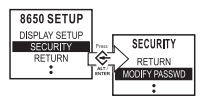
The settings in the front panel SECURITY menu allow you to:
- Modify the existing meter password or reset it to the factory default.
- Enable web browser configuration on the meter.
A valid password is required in order to enter the SECURITY menu. The default password is 0 (zero).
See Cybersecurity for information on meter security, including security recommendations, password best practices and instructions on configuring security through the front panel.
If your device’s front panel or user passwords are lost, you must return the device for factory reconfiguration, which resets your device to its factory defaults and destroys all logged data.
notice
data Loss
Record your device's front panel and user password information in a secure location.
Failure to follow these instructions can result in data loss.