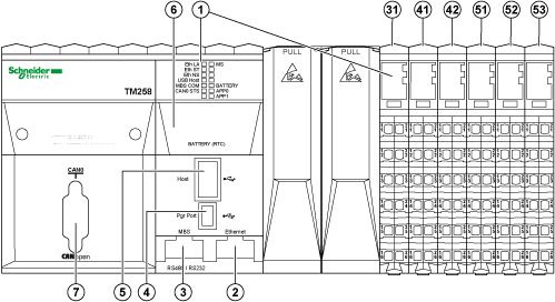
The following illustration shows the different components of the TM258LF42DT4L:

|
N° |
Designation / Description |
Refer to |
|---|---|---|
|
1 |
LED status |
|
|
2 |
Ethernet port / Type RJ45 |
|
|
3 |
Serial line / Type RJ45 (RS232 or RS485) |
|
|
4 |
USB programming port /For terminal connection to a programming PC (EcoStruxure Machine Expert) |
|
|
5 |
USB host / For memory key management |
|
|
6 |
Battery |
|
|
7 |
CAN 0 Port / Male Sub-D 9 CANopen Master |
|
|
31 |
Controller Power Distribution Module / For connecting external power supplies |
|
|
41 |
Embedded Expert I/O modules / 5 fast inputs, 2 regular inputs, 2 fast outputs |
|
|
42 |
||
|
51 |
Embedded Regular Input module / 12 digital inputs |
|
|
52 |
Embedded Regular Output module / 12 digital outputs |
|
|
53 |
Embedded Regular Input module / 4 analog inputs (12-bits) |
General Description

The following table describes the controller status LEDs:
|
Marking |
Description |
LED |
|
|---|---|---|---|
|
Color |
Description |
||
|
MS |
Module status |
Green / Red |
See MS status LED below |
|
BATTERY |
Battery status |
Red |
On when RTC battery needs to be replaced |
|
APP0 |
Application LEDs |
Green / Red |
Managed by user application |
|
APP1 |
|||
The following table describes the MS status LED:
|
Status LED |
Controller State |
Prg Port Communication |
Application Execution |
|---|---|---|---|
|
Flashing green / red |
BOOTING |
No |
No |
|
Flashing red |
INVALID OS |
Restricted |
No |
|
Single flash green |
EMPTY |
Yes |
No |
|
Green ON |
RUNNING |
Yes |
Yes |
|
3 flash green |
RUNNING with Breakpoint |
Yes |
Restricted |
|
Flashing green |
STOPPED |
Restricted |
No |
|
Single flash red |
HALT |
Yes |
No |
|
Rapid flashing red |
REBOOT after a hardware error has been detected |
Yes |
No (Empty) |
|
Red ON |
HALT after system error detected |
No |
No |
|
OFF |
No power |
No |
No |
|
Green / with single flash red |
RUNNING with external error detected Or different Boot Project Or no Boot Project |
Yes |
Yes |
|
Flashing green / with single flash red |
STOPPED with external error detected |
Restricted |
No |
NOTE: For further details on controller states, refer to the Operating Mode discussion in the Programming Guide for your particular controller.
For further details on the following LEDs:
oEth LA, Eth ST and Eth NS, please refer to Ethernet Port - Status LEDs.
oUSB Host, please refer to USB Host Port - Status LED.
oMBS COM, please refer to Serial Line Port - Status LED.
oCAN0 STS, please refer to CAN Port - Status LED.
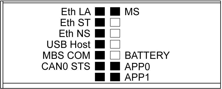
Identifying the logic controller
The following illustration shows the LEDs on the front panel display:

The LEDs flash when the logic controller is being identified. For more information, refer to EcoStruxure Machine Expert Programming Guide.
The following table describes the controller states:
|
State |
Description |
|---|---|
|
BOOTING |
The controller executes the boot firmware and its own internal self tests. It does not execute the application nor does it communicate. It then checks the checksum of the firmware and user application. |
|
INVALID_OS |
The Operating System is not valid. The controller can not execute an application. Communications are restricted. |
|
EMPTY |
The user application is not valid or a hardware error has been detected. The controller does not execute the application but it can communicate. |
|
RUNNING |
The controller executes the application. |
|
STOPPED |
The controller has a valid application that is stopped. |
|
HALT |
The controller has detected an application or system error and has ceased application execution. |
NOTE: For further details on controller states, refer to the Operating Mode discussion in the Programming Guide for your particular controller.
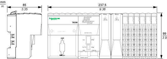
The following illustration shows the external dimensions of the controller:

The following table describes the weight of the TM258LF42DT4L:
|
Weight |
||
|---|---|---|
|
TM258LF42DT4L |
770 g (24.7 oz) |
|